Introduction
This guide will explain and demonstrate how to configure the Microscan ID40 barcode scanner to read, decode and store the barcode on the NJ/NX programmable logic controller.
Please link any other KB articles or prior knowledge here which are referenced here
Further Reading
OMRON NX-Series EtherNet/IP Coupler Unit - User's Manual
OMRON Microscan ID40 – User’s Manual
OMRON Microscan ID40 eds file and Documentation
Procedure
Step1 - Microscan ID40 Barcode Scanner Configuration
Power up and connect the ID40 barcode scanner. Run Microscan Device Discovery Utility. This will load up a web browser with address localhost:8992. You should see the connected Microscan device as seen below.
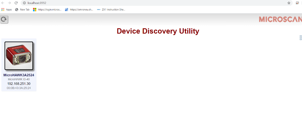
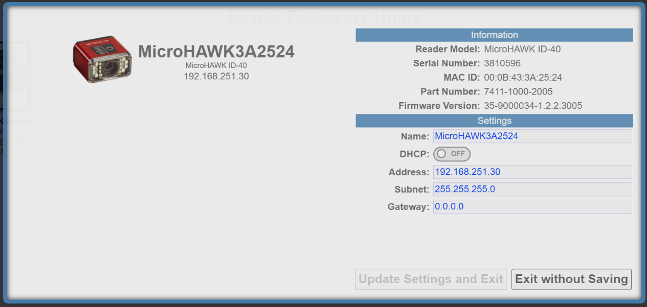
Double click on the connected device to change the network settings. In this example, the IP address is set to 192.168.251.30 which is on the same network as the NX102 Port 2.
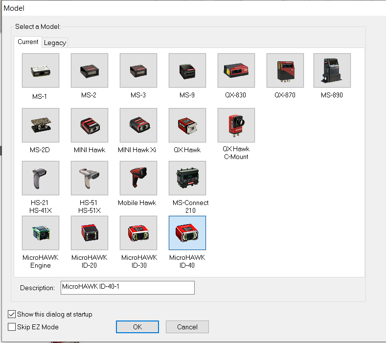
Run Microscan ESP and select the ID40 model hit OK then YES to connect to the scanner.
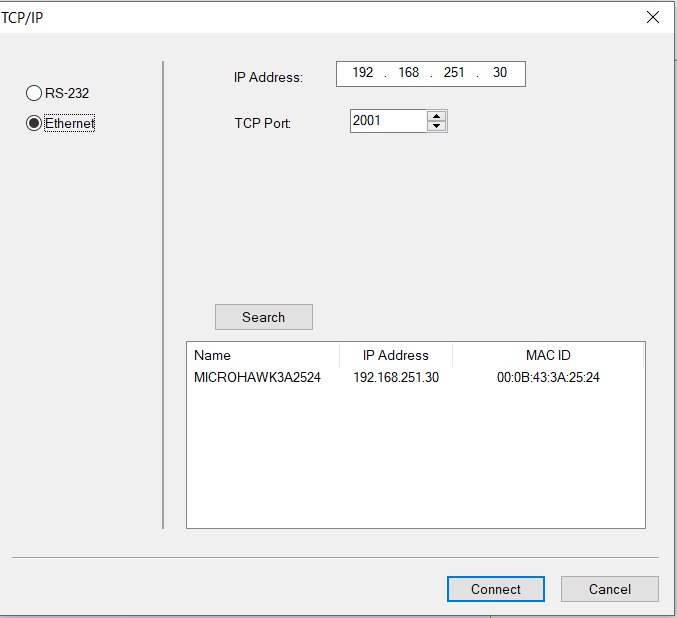
Under Ethernet put the IP address of the scanner that was previously set (192.168.251.30). TCP Port should be default at 2001.
Or alternatively press Search to find the IP address of the scanner. Click Connect.
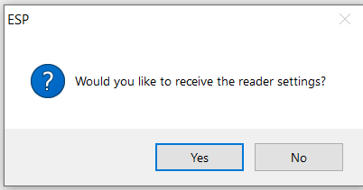
Click YES when asked to receive reader settings.
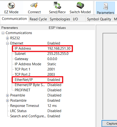
Under Parameters -> Ethernet the IP address should show 192.168.251.30 and EtherNet/IP should be enabled.
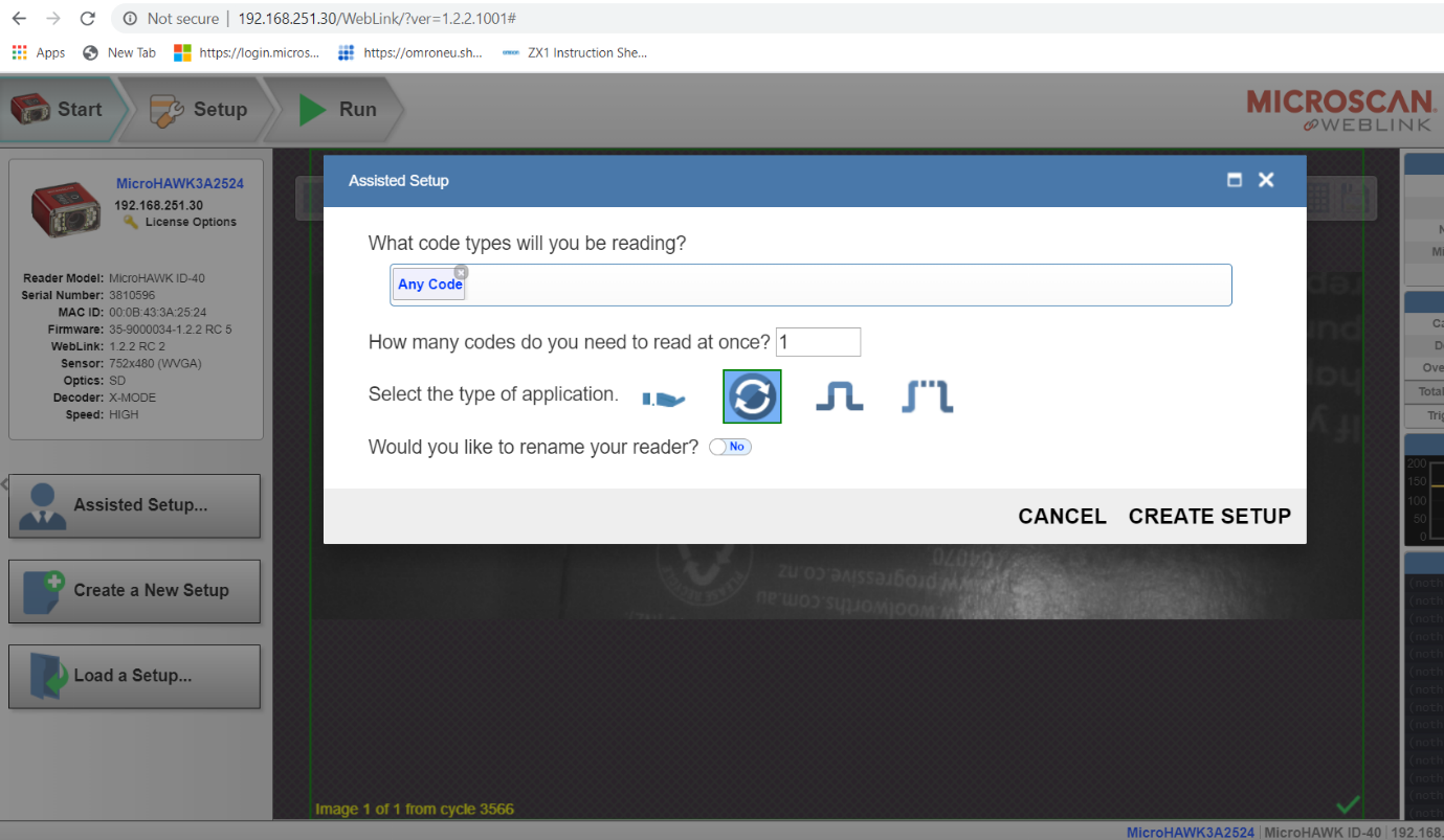
Test your connection settings by using Microscan WebLink. Type in the IP address of the scanner into a browser (http://192.168.251.30).
Under the Start tab click on Assisted Setup.
For this setup we will read Any Code, 1 code at a time for a Continuous measure application. Once set, click Create Setup.
Network setup of the Microscan ID40 barcode scanner is now complete.
Step 2 - Installing the ID40 EDS file
In a browser visit the Microscan download center via this link https://www.microscan.com/en-us/support/download-center. Scroll down until 2D Barcode Readers is visible and click on the red DRV box to download the drivers.
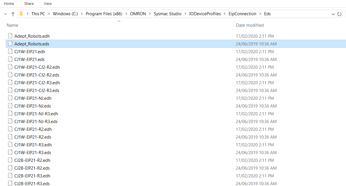
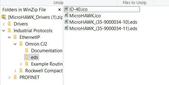
Once downloaded open and navigate through the compressed file Industrial Protocols -> EthernetIP -> Omron CJ2 -> eds. Extract the two .eds files to Sysmac Eds folder (depending on your Sysmac installation directory) default would be:
C:\Program Files (x86)\OMRON\Sysmac Studio\IODeviceProfiles\EipConnection\Eds
Step 3 - NJ/NX Configuration
EtherNet/IP Settings
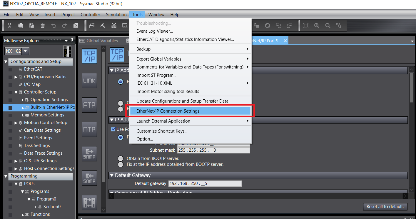
Under Tools->EtherNet/IP Connection Settings
Double click the port you want to use with the ID40, in this case since its on the 192.168.251.XXX network – we use Port 2.

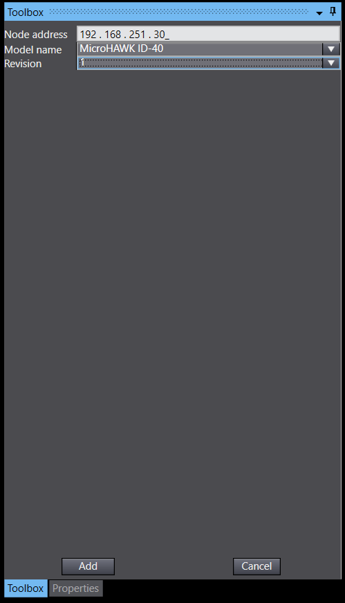
On the right side under Toolbox -> Target Device press the add button.
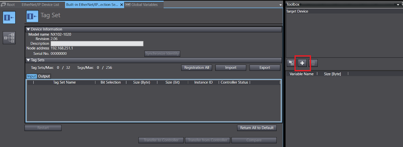
Enter the IP address of the ID40 192.168.251.30
Model Name from the drop-down menu MicroHAWK ID-40
Revision: 1
Then click add.
On the Connection page, click and drag the Target Device just added to the central workspace. This will add the MicroHawk device with pink/empty fields as seen below.
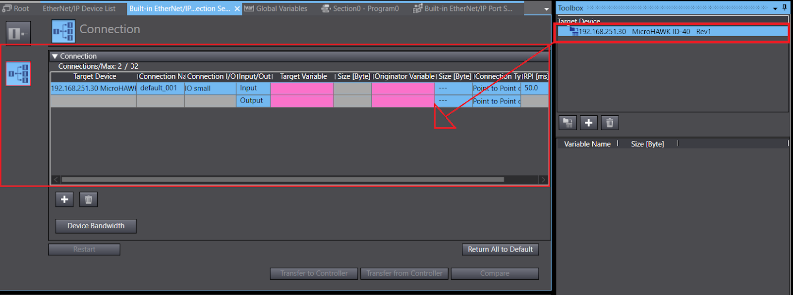
Input: Target Variable: 100
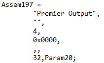
Output: Target Variable: 197
The byte sizes will automatically fill according to the EDS file.
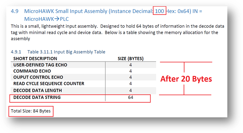
From the EDS documentation for the ID40, the input can be seen with instance value 100. Decode Data String can be found 20 bytes down.
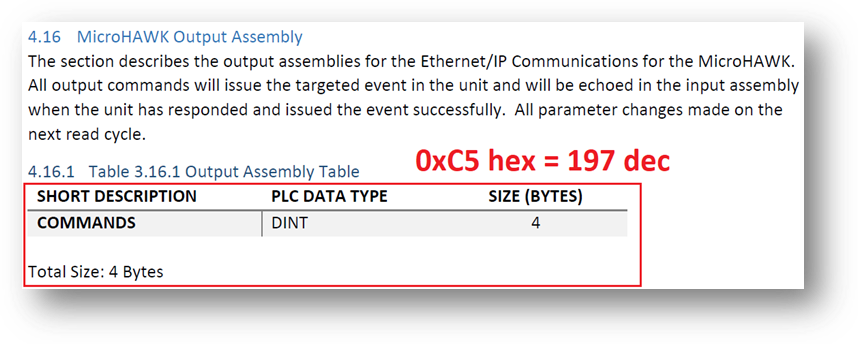
The output tag sits at 197 with a total of 4 bytes.

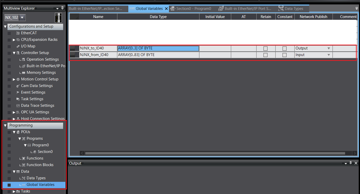
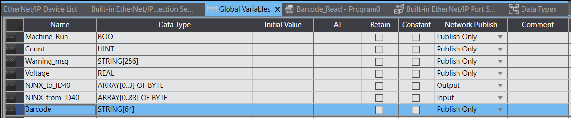
From these Input and Output byte sizes, create two Global Variables
| Global Variable Name | Data Type | Network Publish |
|---|---|---|
| NJNX_to_ID40 | ARRAY[0..3] OF BYTE | OUTPUT |
| NJNX_from_ID40 | ARRAY[0..83] OF BYTE | INPUT |
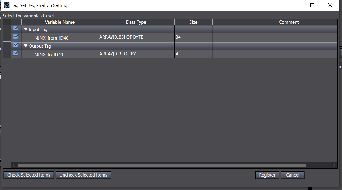
Inthe Built-in EtherNet/IP Port Settings – Port 2 Connection Settings - NX102 tab under Tag Set.
Click Registration All then on the next window click Register
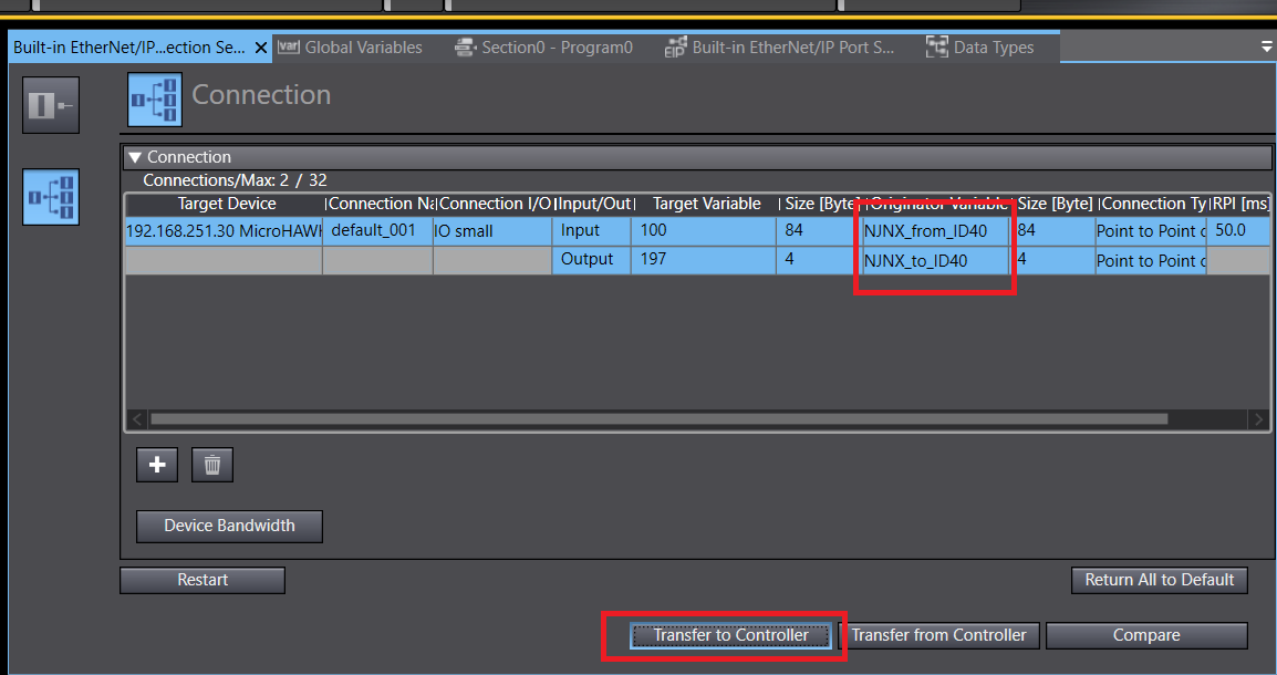
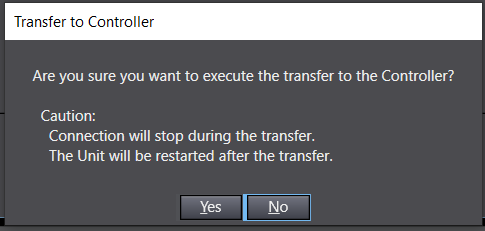
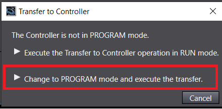
Under Built-in EtherNet/IP Port Settings -> Connection. Under Originator Variable we can now add the registered variables NJNX_from_ID40 for Input and NJNX_to_ID40 for Output. Go online and Transfer to Controller. Please note that the connection will drop and the unit will restart after the transfer. Transfer via Program Mode when prompted.
Test EtherNet/IP Data
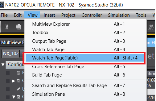
From the main tool bar click on View -> Watch Tab Page (Table) or ALT + 4
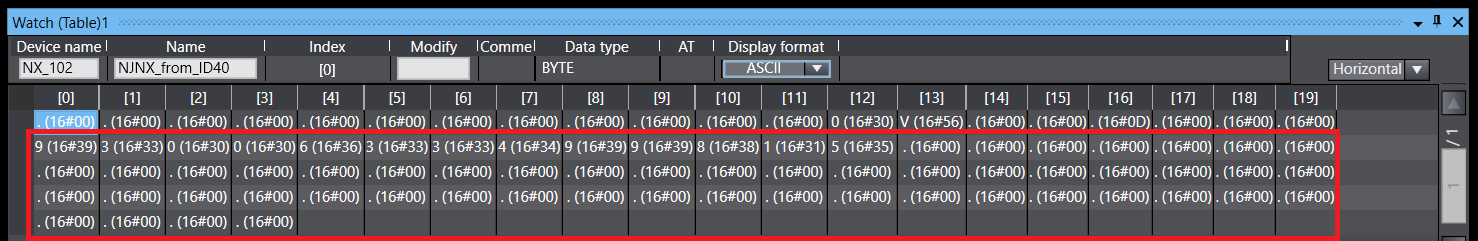
In the Watch table enter the name of the global variable NJNX_from_ID40. As seen below, the decode string can be seen after 20 bytes of data (highlighted in red)
Step 3 - NJ/NX Programming to read Barcode Data
Create a new global variable named Barcode.
Under the Multiview Explorer window
Programming -> Data -> Global Variables right click and Create New. Barcode of STRING[64] and have it set to Publish Only.
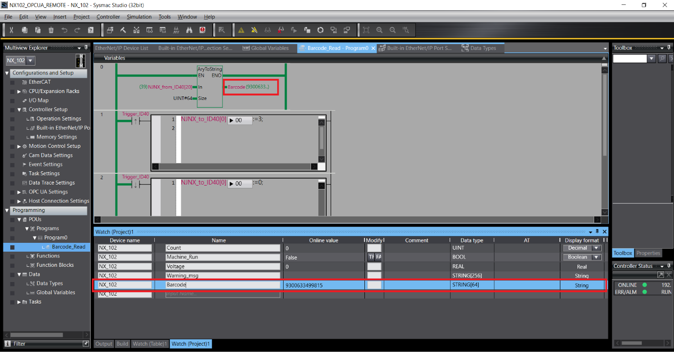
Since the data coming in from the ID40 is stored in the variable NJNX_from_ID40 which is an ARRAY_OF_BYTE(s) with size of 84. Extract the decoded string data starting from the 21st byte. To do this, use the AryToString function.
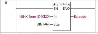
| Parameter | Setting Value | Description |
|---|---|---|
| In | NJNX_from_ID40[20] | AryToString converts the NJNX_from_ID40 (size of 84 byte array), starting from the [20] 21st element since NJNX_from_ID40[0] is the 1st element |
| Size | UINT#64 | 84 bytes - 20 bytes = 64 size of the barcode array |
| OutputVariable | Barcode | where the converted output array is stored |
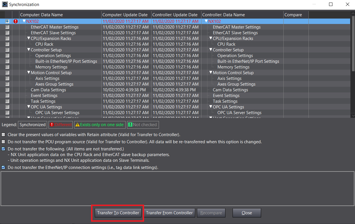
Submit the changes by working online, Controller -> Online then synchronize to the controller: Controller -> Synchronize -> Transfer To Controller.
 asd
asdOpen a watch tab page (Alt + 4) or View -> Watch Tab Page and add the Barcode variable to watch
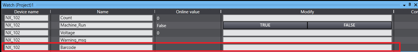
Now point the ID40 to a barcode, if it picks up the barcode – the Online value will change to the Barcode string. In this example: 9300633499815