Introduction
This guide provides a series of steps that show how to use the Position Correction functionality of Microscan MV Cameras, using AutoVISION. In order to use Position Correction, the Locate Shape functionality must also be used, and is therefore demonstrated below.
The purpose of Position Correction is to enable greater robustness in detection solutions, by allowing a degree of freedom in the placement of elements to be detected within a camera's field of view.
Pre-Requisites
Basic knowledge of computer operation.
Procedure
Step 1 - Download and Install Software
Locate the appropriate version of the AutoVISION software from the following website.
Ensure that the version supports the specific model of the Microscan camera prior to downloading.
Once downloaded, install the software by double-clicking on the downloaded executable file.
Step 2 - Camera Setup
The Microscan MV Camera has two cables. One cable is used to connect power to the camera, the other is used to communicate between the camera and a PC, using ethernet.
Connect these cables as appropriate.
Physically position the camera in order to capture the target image. This position will be refined in a later step.
Step 3 - Connecting to the Camera
Run the AutoVISION software on the PC.
Once the software is running, select the camera under the 'Connect' heading on the screen.
If the PC cannot connect to the camera, see this article for resolutions to this issue.
Step 4 - Creating a Job
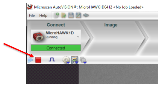
When connected, the camera may be in 'Run' mode. Click the 'Stop' button, as shown in the below image, to ensure that the camera is ready for programming.
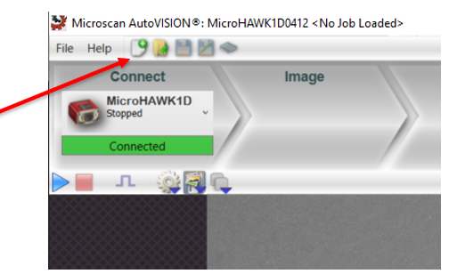
Following this, click the 'Create a New Job' button to create a new job, as shown in the below image.
Step 5 - Image Calibration
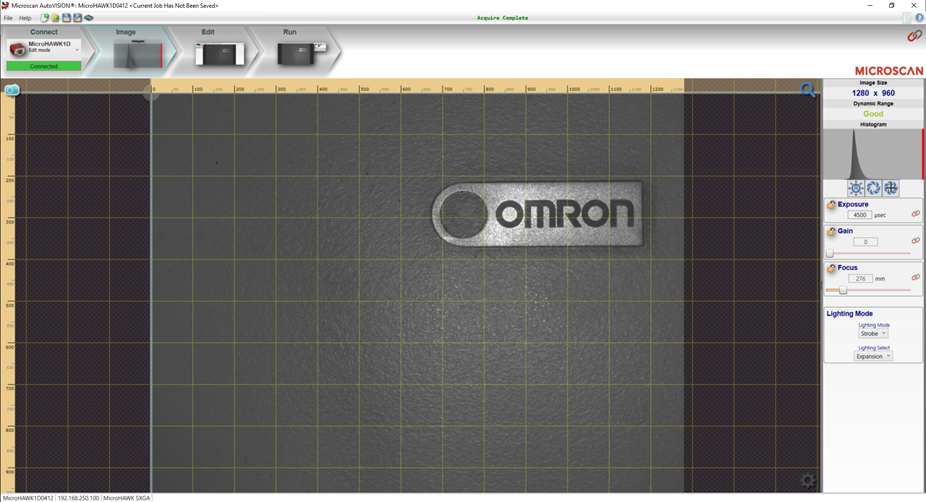
On the creation of a new job, the camera will automatically capture an image. This image can be recaptured by clicking on the blue camera icon in the top left of the screen. Hovering the mouse pointer over this icon will provide the option to use a live feed, or trigger inputs to enable the capture.
The camera's position can be physically adjusted at this point, to ensure that the desired image is captured. Note the field of view of the captured image.
On the right-hand side of this screen, as shown in the below image, various settings can be configured to change the appearance of the image. It is recommended to use the 'Auto-Calibration' button, located directly beneath the histogram, and then manually adjust the settings to obtain a reasonable image.
Step 6 - Creating and Teaching a Locate Shape Function
In order to create a Locate Shape Function, select the 'Edit' element of the AutoVISION software, located at the top of the screen. This will present a toolbar beneath the 'Edit' element, as shown in the image below.
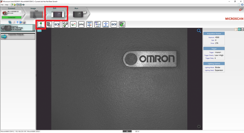
Click on the 'Locate Shape' tool, located on the left of the toolbar.
This will insert a Locate Shape function into the processing flow, located on the left side of the screen. In addition, it will insert two red rectangle areas onto the captured camera image. One rectangle is labelled 'Locate Shape', and the other is labelled 'Template'.
The 'Locate Shape' rectangle represents the area of the captured camera image where the Locate Shape Function will search for the taught shape.
The 'Template' rectangle represents the area of the captured camera image which the Locate Shape Function will use to be taught the shape which it will attempt to locate.
Adjust the size and position of these two rectangle areas by clicking and dragging the corners of those areas.
Ensure that the 'Locate Shape' rectangle covers the area of the captured camera image where it is expected that the shape to be detected will be in normally. It is good practice to keep this area relatively large, to ensure that the detection is robust.
Ensure that the 'Template' rectangle covers only the shape which is to be located. It is important to keep this area as small as possible to reduce the possibility of noise in the taught shape.
Once the rectangles have been appropriately adjusted, click on the small red icon at the upper edge of the 'Template' rectangle, as indicated in the below image.
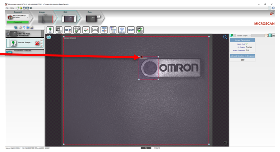
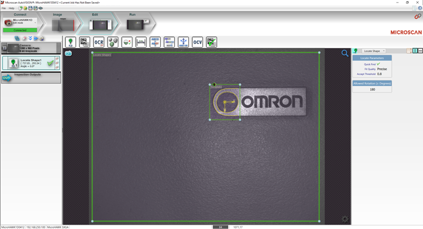
This will teach the Locate Shape Function the shape to search for. Once complete, the rectangles will turn green, and the detected edges of the taught shape will appear in yellow, as shown in the below image.
Ensure that the taught shape is appropriate for the application. If there is too much noise, or if the shape does not appear robust, adjust the borders of the 'Template' rectangle and re-teach the shape to the function.
Note that the function's parameters are displayed on the right side of the screen, with a zoomed image shown below.
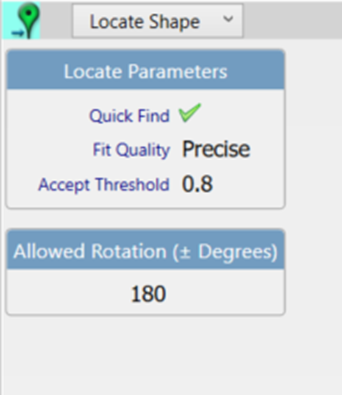
These parameters can be used to change the quality of the search algorithms, including the ability to detect shapes with slight variations from the taught shape. Additionally, the search algorithms can be given the freedom to search for rotated shapes, up to +- 180 degrees.
Step 7 - Position Correction Function
At the top left of the Locate Shape Function parameters, as shown in the previous image, a green map marker is present, with a cyan background. This indicates that the Locate Shape Function can be used as a coordinate system. Note that if the background is not cyan, clicking on the map marker will change the setting appropriately, otherwise no action is necessary.
In the processing flow on the left side of the screen, a numeral will be shown on the Locate Shape function. This numeral references the coordinate system based on the function, and is shown in the below image, with the numeral '1'.
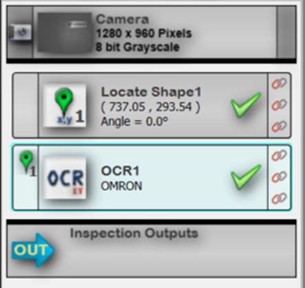
As additional functions are added to the processing flow, they may use the coordinate system generated by the Locate Shape Function. This can be seen in the above image, with the newly added OCR1 Function showing a green map marker with the numeral '1' to its left. This can be deactivated, or changed to other coordinate systems by clicking on that marker.
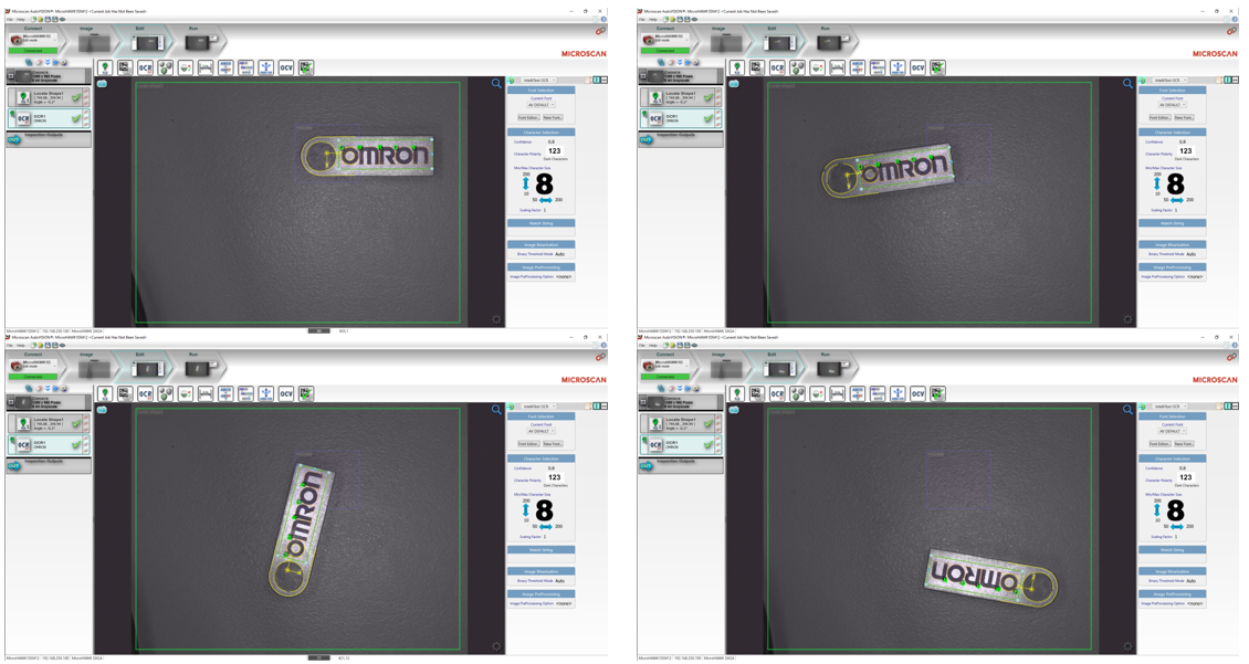
This has enabled the Position Correction functionality of AutoVISION and Microscan Cameras, which allows for greater robustness in detection solutions.
See the below image for examples of this robustness.