Introduction
This document highlights the methods of:
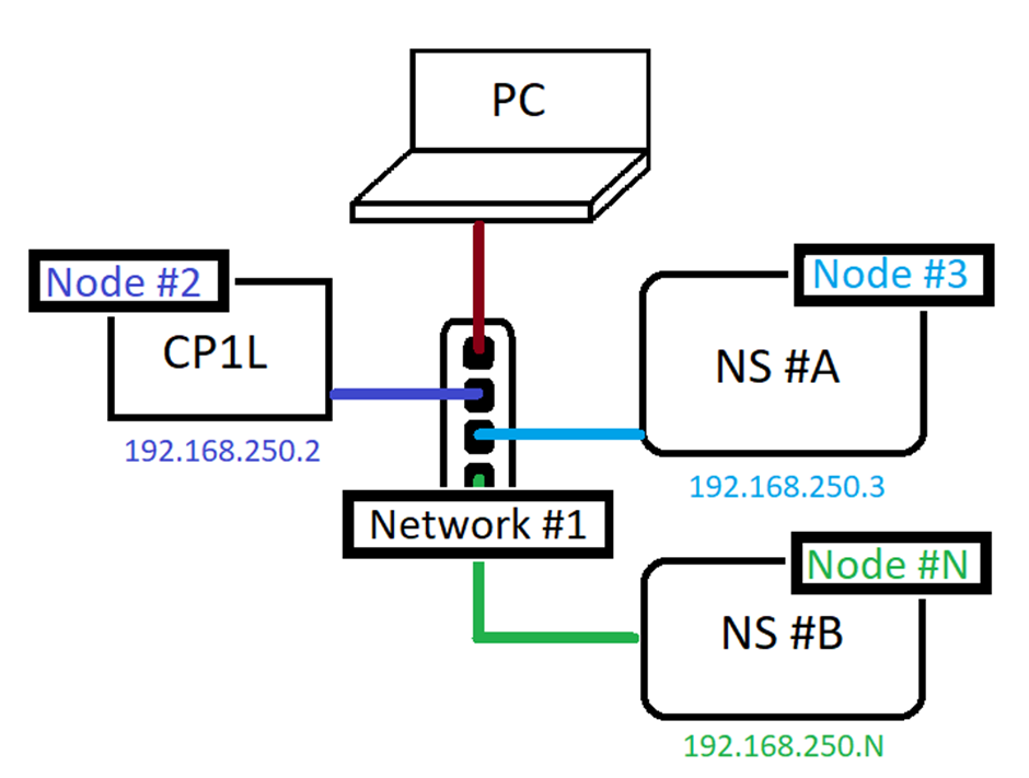
- Configuring CP1L ethernet/FINS communications settings: 192.168.250.2
- Configuring NS10 ethernet/FINS communications settings: 192.168.250.3
- Setting a routing table to set both devices on the same network: #1
Pre-Requisites
Note that each device has their own individual node id number. As seen in the image below N cannot be 2 or 3 since CP1L and NS #A are using numbers 2 and 3.Further Reading
Any manual references can be put here. Note you can put hyperlink to the manuals stored on eStore once this is setup
Procedure
Step 1 - CP1L-E Configuration
For the above example, change the CP1L’s IP address and FINS Node number.
From PLC Settings > Built-in Ethernet tab, set the following.
CP1L Ethernet Settings | |
IP Address |
192.168.250.2 |
FINS Node No |
2 |
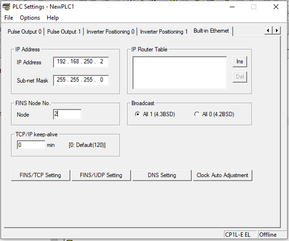
Transfer these settings and power cycle the PLC.
DeleteStep 2 - NS Screen Configuration
For the CP1L to identify and communicate with the NS screen, it needs to know which network address it is on and what device/node number.
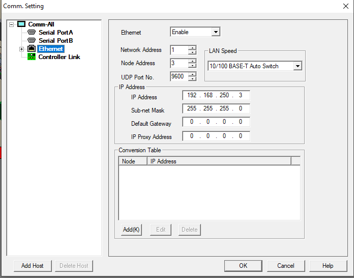
In CX-Designer, PT > Communications Setting under Ethernet make sure it is enabled.
Since network 1 will be used, set the Network Address to 1 and the Node Address to 3. Since the Node Address is 3, the IP Address will be 192.168.250.3 as seen below.
NS Ethernet Settings |
|
Network Address |
1 |
Node Address |
3 |
IP Address |
192.168.250.3 |
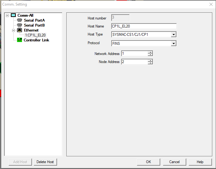
Next, the host needs to be configured. Expand Ethernet>[Right-Click] Add. As seen below host CP1L-EL20 is added. Since this example is working with a CP1L, the host type needs to be SYSMAC-CS1/CJ1/CP1. Protocol set to FINS, Network Address is 1 and the Node Address of the host (CP1L) is 2.
NS Host (CP1L_EL20) Settings |
|
Host Type |
SYSMNAC-CS1/CJ1/CP1 |
Protocol |
FINS |
Network Address |
1 |
Node Address |
2 |
Step 3 - CX Integrator - Setting the Routing Table
Use CX Integrator to set the CP1L’s Network Address to 1 - the same network for the NS.
Network > Communication Settings
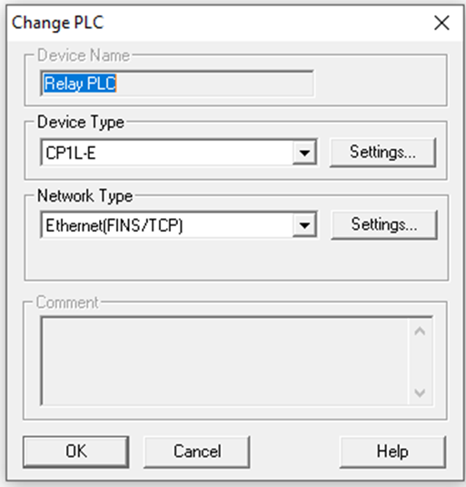
Choose the correct PLC CP1L-E. Click Settings and under CPU Type choose EL.
For Network Type choose Ethernet(FINS/TCP), Settings > Driver tab choose either Direct Connection or Hub Connection. Hit OK and OK again
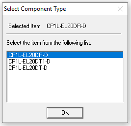
Choose the correct component type depending on the PLC type then hit ok
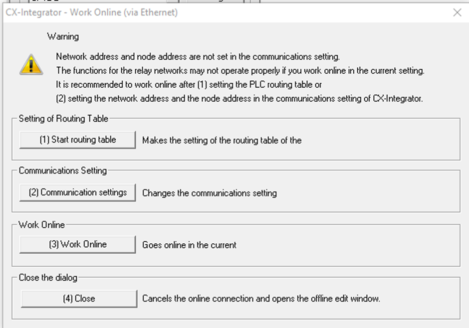
Network > Work Online
Select (3) Work Online
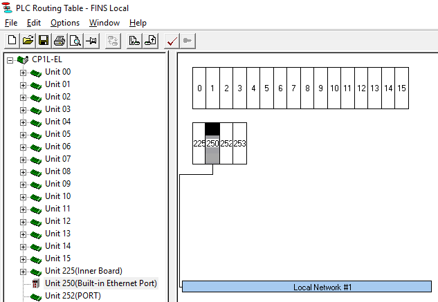
While connected go to Tools > Start Routing Table
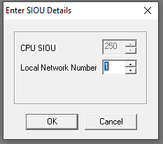
Right click on unit 250(Built-in Ethernet Port) and select Insert CPU SIOU.
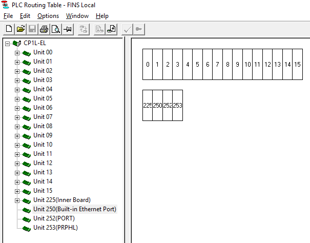
Put 1 in the Local Network Number since the devices are all set to network 1
The following window will show Local Network #1 connected to 250 (Built-in Ethernet Port)
All that is left is to transfer this to the CP1L Options > Transfer to PLC
Your setup is now complete and both devices are now able to talk to each other.
Delete