Introduction
This document describes the procedure to configure and connect a CP1[] series PLC to an RX2 inverter drive for simple motion control using Modbus RTU. This example is intended for a new CP1/RX2 user and illustrates easy programming and configuration for simple inverter motion control of a new system.
Overview
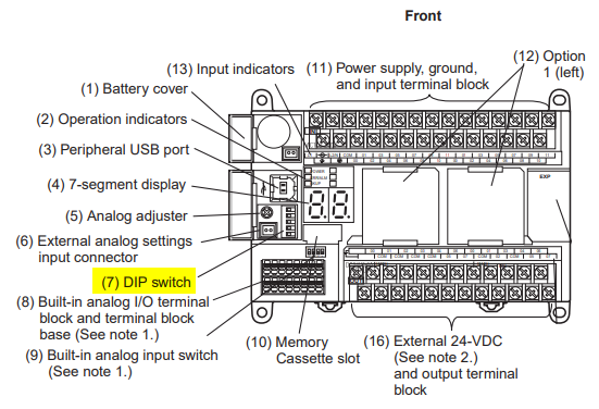
The example provided below uses the CP1[] Series PLC with a CP1W-CIF11 installed in the rightmost option board position (slot 2). The PLC uses the CP1W-CIF11 serial option module to communicate with the RX2 inverter using the Modbus protocol for functions such as start/stop, speed control, status monitoring and error reset. Up to 31 inverters may be connected to a Modbus "master" (the CP1[] in this example) using an shielded, twisted-pair cable.
A basic CX-Programmer project is provided and detailed for this tutorial. Typically, an HMI or other external user input device is needed for real application, but this tutorial does not cover such detail and only includes simplified programming for trial operation.
Applicable Hardware
PLC
- CS1*-CPU**H Unit version 3.0 or higher
- CJ1*-CPU**H Unit version 3.0 or higher
- CJ1M-CPU** Unit version 3.0 or higher
- CP1H
- CP1L (except 10 points CPU)
- CP1L-E
Serial Communications Units
- CS1W-SCU21-V1
- CJ1W-SCU21-V1
- CJ1W-SCU41-V1 Unit Version 1.2 or higher
- CS1W-SCB21-V1
- CS1W-SCB41-V1 Unit Version 1.2 or higher
- CP Series CPU serial port
Further Reading
3G3RX2 Users Manual(See Section 9):
https://www.edata.omron.com.au/eData/Inverters/I620-E1-01.pdf
CP1L Operation manual(See section 2-1-3):
https://www.edata.omron.com.au/eData/PLCs/CP1/W462-E1-10.pdf
Procedure
Wiring and Connection Settings
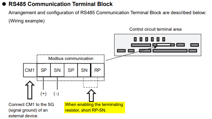
The RX2 inverter will be controlled entirely by MODBUS commands over the RS485 serial communication link (to the CP1[] PLC), so no I/O wiring is required. The communication wiring should connect the ‘SN’ and ‘SP’ terminals of the RX2 and the screw terminals of the CP1W-CIF11 RS422/485 communications option module, fitted in the right-hand slot of the CP1[]. Use the following steps to connect the CP1W-CIF11 to the RX2 inverter.
DIP Switch Settings on the CP1W-CIF11
1. Short terminals SP and SN to enable the terminating resistor. The connection can be seen as below:
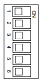
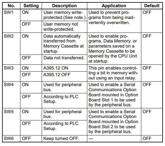
2. Set the DIP switches on the rear of the CP1W-CIF11 unit according to the diagram below.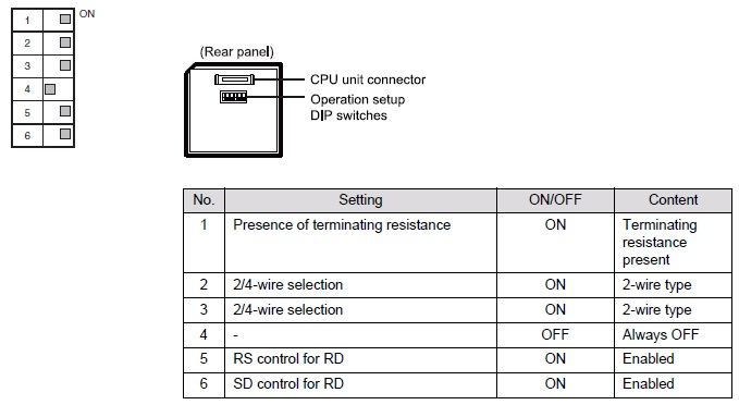
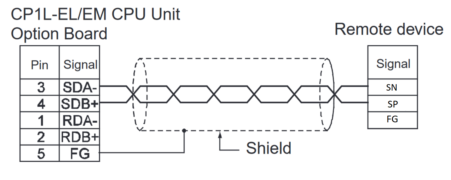
Wiring:
3. Connect the RX2 terminal labeled "SN" to the CP1W-CIF11 terminal labeled "SDA-".
4. Connect the RX2 terminal labeled "SP" to the CP1W-CIF11 terminal labeled "SDA+".
Dip Switch Settings on the CP1L/CP1H
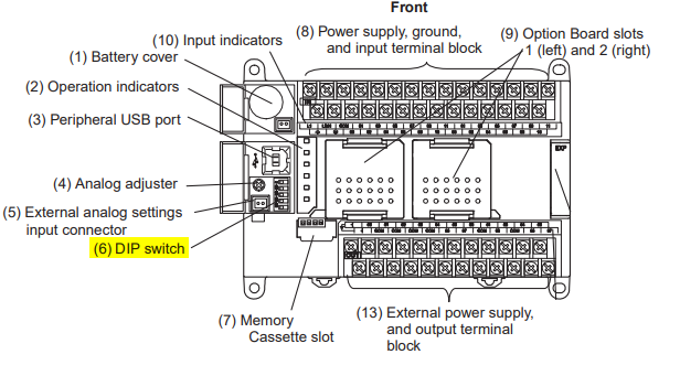
1. Locate the dip switches on the CP1L:
or on the CP1H:
2. Make sure the dip switches are in the following position:
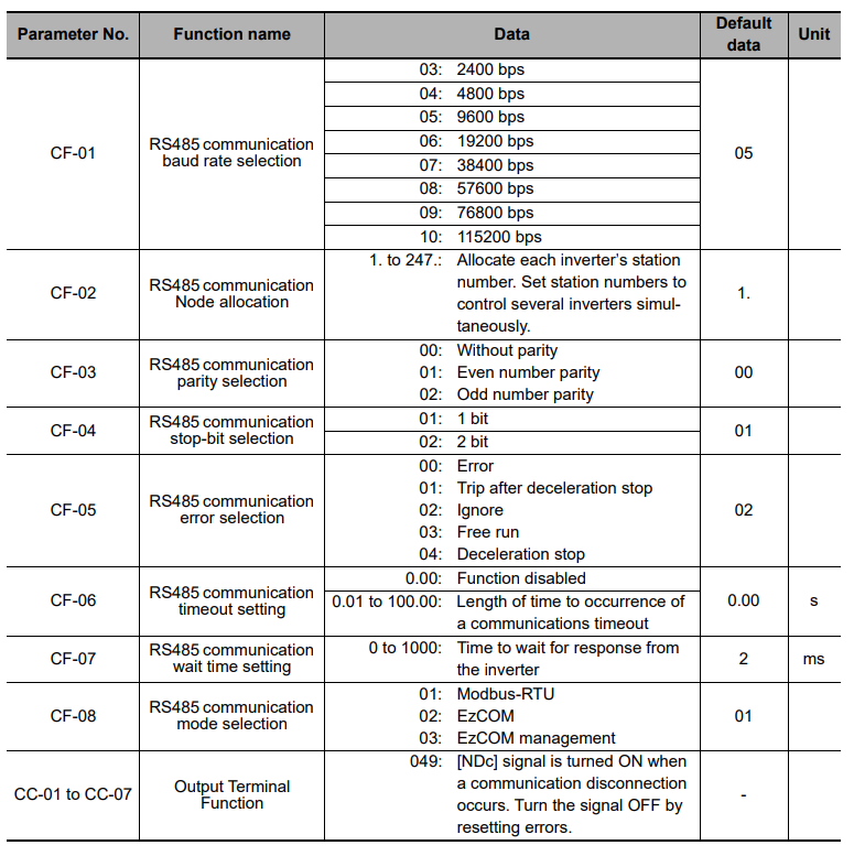
RX2 Parameters
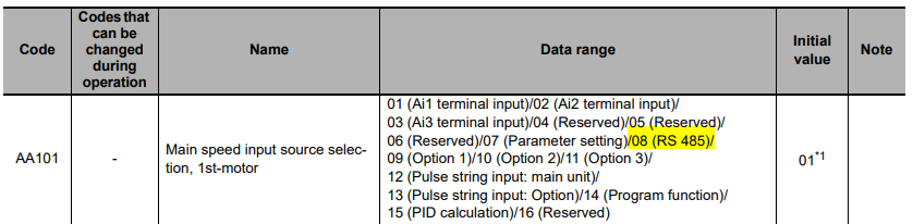
By default, the RX2 is set to accept speed reference and run command signals from the built-in front panel keypad and external digital input signals. In order for the RX2 to be controlled entirely over Modbus, the following parameters (AA101and AA111 highlighted in yellow, below) must be changed. Please be sure to cycle the power to the inverter after changing these parameters in order for the new settings to take effect. The sample CX-Programmer project uses Modbus settings of 9,600bps (baud rate), 8 data bits, 1 stop bit and no parity, and also assumes that the RX2 has a node number (network address) of 1. Therefore, no other parameters need to be changed from the defaults, as they already match these settings.
Please refer to section 3-1-4 of the RX2 User’s Manual (Cat. No. I620-E1-01) if you are unfamiliar with the operation of the front panel keypad.

PLC Program
The included PLC Program is completely documented for an easy understanding of functionality and operation. This program incorporates a Function Block that provides control and status monitoring of the RX2 using the Modbus protocol.
Configure the serial port as shown below, if the CP1W-CIF11 is connected to port 1(left), configure Serial Port 1. Otherwise, configure Serial Port 2.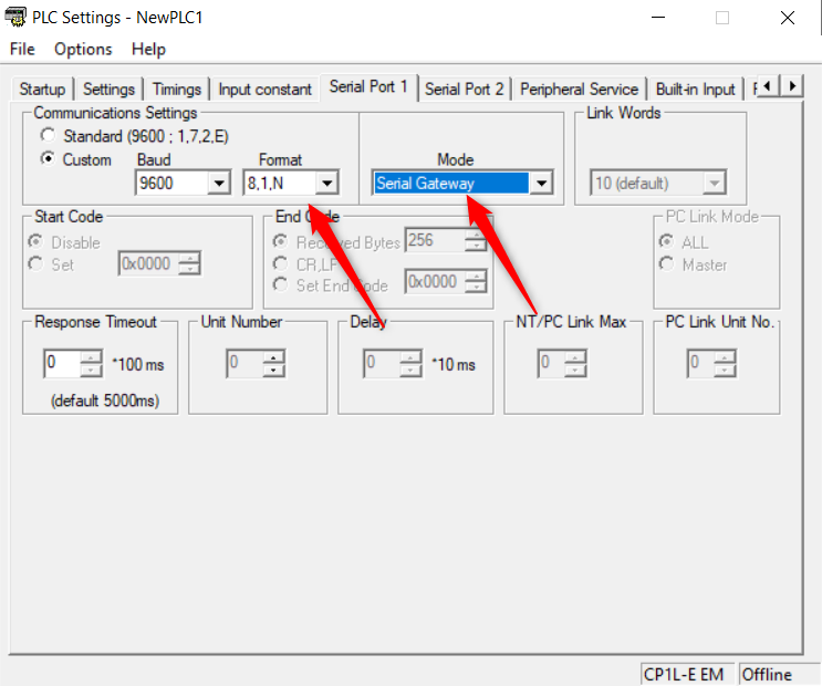
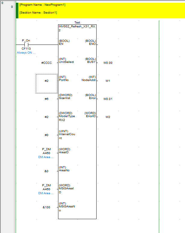
In our example we will set the inputs to the INV002_Refresh FB as shown below.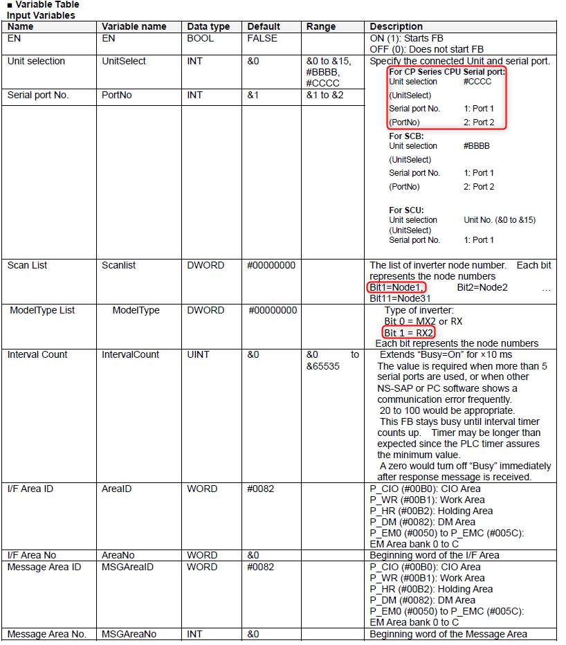
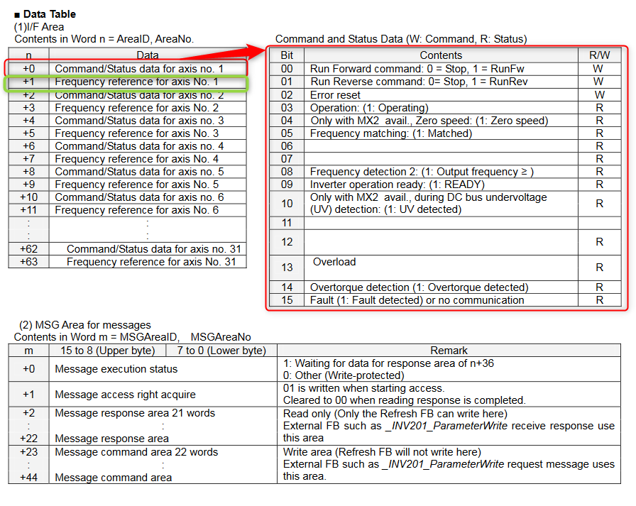
The tables below show the data table and command word structure. The word n=0 is the command word, and n=1 is the reference frequency. In this example we set the Data table area to D100, so to set the speed to 10Hz, we would write &1000 to D101. We would set D100.00 to TRUE to set the drive to Run Forward.
Delete
The example program and function blocks are attached blow: