1 Introduction
This article shows the basic steps for configuration of a Rockwell Automation PLC to connect to the OMRON NX‐EIC202 EtherNet/IP coupler. The guide will assume the hardware installation has already been completed following [W536].
This document has been made using the Allen‐Bradley 1769‐L23E‐QB1 Controller, but will apply to other Rockwell based controllers as well.
The following is required:
- OMRON NX‐EIC202 EDS file.
- Rockwell Automation RSLogix5000 tool.
- OMRON Sysmac Studio NX‐I/O edition.
Please be sure to read the related manuals to use the NX‐EIC202 Unit safely and properly.
| Reference | Name | Cat. No. |
| [1] | NX‐Series EtherNet/IP Coupler Unit User’s Manual | W536 |
2 NX-EIC202 Configuration
Use the following procedure to prepare the Unit for use. Refer to the reference sections for details on the indicated steps.
| Step | Item | Section |
| 1 | Installation: Install the EDS file in Logix5000 | 2.1 |
| 2 | Set IP address using the rotary switches | 2.2 |
| 3 | Configure the NX-EIC202 with the NX Configuration in Sysmac Studio | 2.3 |
| 4 | Configure EIP connection | 2.4 |
| 5 | Use NX-EIC202 IO data in the PLC program | 3 |
2.1 [RSLogix] Install EDS file
Follow the steps below to install (a new version of) an EDS file withing RSLogix5000. Both installation and de-installation of the EDS file is done by the EDS Hardware Installation Tool (Tools menu).
Warning
A custom version of the EDS file is used for communication to Rockwell PLCs. If there are any existing standard EDS files for the NX-EIC202 installed, please ensure that it is uninstalled, and the nodes created referencing the older file have been deleted.
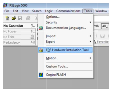
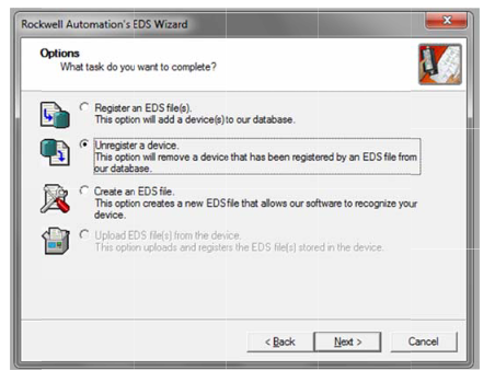
- To delete the old EDS file, select the Unregister a device option.
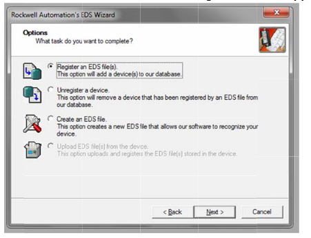
- To Install the new EDS file, select the Register an EDS file(s).
2.2 Setting the NX-EIC202 IP address
Perform the following steps to change the IP address of the NX-EIC Unit in the Rockwell default range (192.168.1.x).
- Set the DIP switch 4 to On
- Set the two rotary switches to the desired IP address (last octet 01 to FE for 192.168.1.1 to 192.168.1.254).
After a power cycle, the new IP address will be active in the unit.
Please see additional information about setting the IP address in the below article.
2.3 [Sysmac Studio] Setting up the Slave Terminal
The NX-EIC202 Operation manual (see[1]) describes the procedure to configure the Slave Terminal (NX-EIC202 and the individual NX Units).
Connect Sysmac Studio using a USB connection then set the NX configuration with the information the following two sections of the original manual:
- Section 9-2 Setting Slave Terminal Parameters
- Section 9-3 Transferring and Comparing Settings
After the NX Configuration is finished, please use the following steps to check the resulting I/O Allocation size of the Coupler.
- In the Multiview Explorer view, right click the EtherNet/IP Coupler and select Display I/O Allocation from the menu.
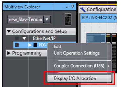
- The I/O allocation indicates the input and output data sizes in bytes for the present configuration.
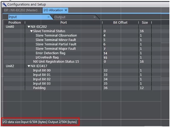
The input and output tag sizes are necessary to configure the EtherNet/IP connection in RSLogix.
2.4 [RSLogix] Configure EIP connection
The main view of the RSLogix5000 software provides the way to add the NX-EIC202 to the PLC's network. Please see below for an example of the main view of the tool.
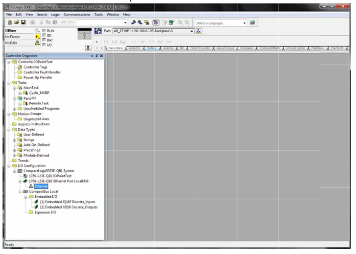
Perform the following steps to add the NX-EIC202 to the network.
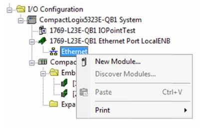
- Select the New Module… function of the Ethernet items context menu.
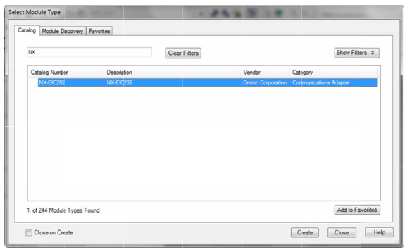
- Select the NX-EIC202 from the list and click Create.
- Enter the common data such as the Name, Description and IP address in the following form.
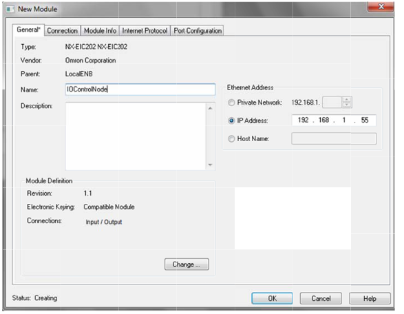
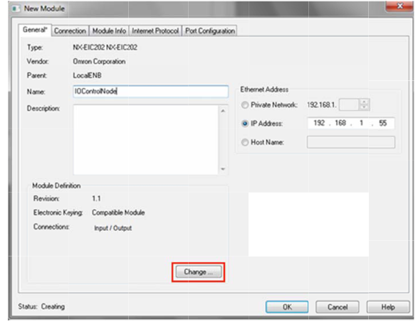
- Click on the Change… button to the the detailed IO data.
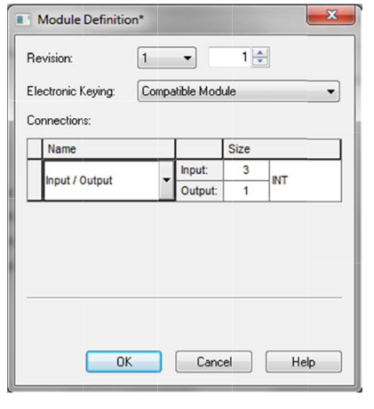
- Please select the correct size of the input and output buffers int he Module Definition window. Use the data as indicated in the I/O Allocation window (see section 2.3). Set the data type to INT and select the correct sizes (note that Sysmac Studio indicates the size in bytes).
Select OK.Information
Most common data types are set to INT which have been proven successful. Some modules require a different data type setting so try SINT if any issues / if adding extra IO cards and configuration no longer works.
- The Connection tab of the New Module window gives the settings of RPI and the input type (Unicase/Multicast). Please fill in according to your requirements.
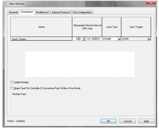
- Click OK to add the NX-EIC202 to the network.
The NX-EIC202 has now been configured. Please follow the standard procude od the Rockwell software to download the conguration to the PLC and the network.
3 NX-EIC202 Operation
The Controller Tags show the Input and Output data allocated to the NX-EIC202.

These tags can be used in the PLC program to use the IO data of the coupler.
NX‐Series EtherNet/IP Coupler Unit User’s Manual W536