Introduction
This article covers how to set up the analog expansion modules for the CP series PLCs.
Step 1
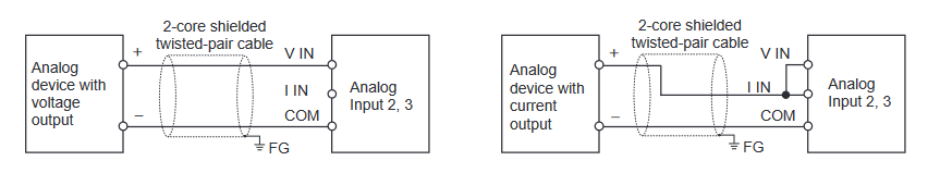
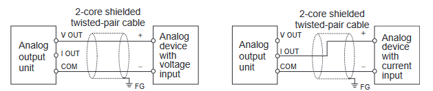
Wire the analog inputs/outputs. See Appendix E.
Step 2
Determine the memory offset of the expansion module. See this article for more details.
Step 3
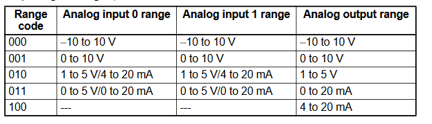
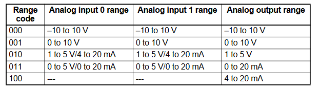
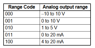
Determine the range codes required for your application. See the below example for determining your range codes. Appendix F contains the full reference of range codes.
Range Code Example
-
Analog Input Module
-
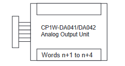
Analog Output Module
-
Analogue Input/Output Module
- Add Button
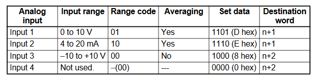
CP1W-AD041 Range Code Example
- Input 1 = -10V to 10V
- Input 2 = 0 to 10V
- Input 3 = 4 to 20mA
- Input 4 = Not in use
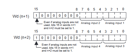
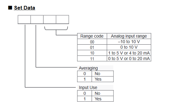
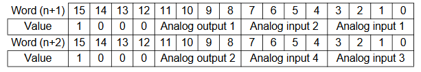
The below graphic shows how the range codes are structured
- Input 1 set data = Input Use(Yes, 1), Averaging (No, 0), Range Code (-10 to 10V, 00)
- Input 2 set data = Input Use(Yes, 1), Averaging (No, 0), Range Code (0 to 10V, 01)
- Input 3 set data = Input Use(Yes, 1), Averaging (No, 0), Range Code (4 to 20mA, 10)
- Input 4 set data = Input Use(No, 0), Averaging (No, 0), Range Code (N/A, 00)
Therefore the n+1 and n+2 are:
| 15 | 14 | 13 | 12 | 11 | 10 | 9 | 8 | 7 | 6 | 5 | 4 | 3 | 2 | 1 | 0 | |
| n+1 | 1 | 0 | 0 | 0 | 0 | 0 | 0 | 0 | 1 | 0 | 0 | 1 | 1 | 0 | 0 | 0 |
| n+2 | 1 | 0 | 0 | 0 | 0 | 0 | 0 | 0 | 0 | 0 | 0 | 0 | 1 | 0 | 1 | 0 |
CP1W-DA041 Range Code Example
- Output 1 = -10V to 10V
- Output 2 = 0 to 10V
- Output 3 = 4 to 20mA
- Output 4 = Not in use
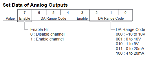
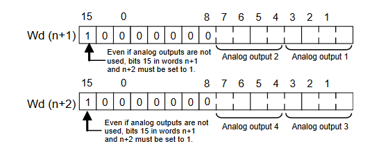
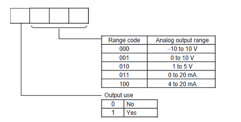
The below graphic shows how the range codes are structured.
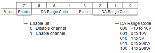
- Output 1 set data = Output Use(Yes, 1), Range Code (-10 to 10V, 000)
- Output 2 set data = Output Use(Yes, 1), Range Code (0 to 10V, 001)
- Output 3 set data = Output Use(Yes, 1), Range Code (4 to 20mA, 100)
- Output 4 set data = Output Use(No, 0), Range Code (N/A, 000)
Therefore the n+1 and n+2 are:
| 15 | 14 | 13 | 12 | 11 | 10 | 9 | 8 | 7 | 6 | 5 | 4 | 3 | 2 | 1 | 0 | |
| n+1 | 1 | 0 | 0 | 0 | 0 | 0 | 0 | 0 | 1 | 0 | 0 | 1 | 1 | 0 | 0 | 0 |
| n+2 | 1 | 0 | 0 | 0 | 0 | 0 | 0 | 0 | 0 | 0 | 0 | 0 | 1 | 1 | 0 | 0 |
-
CP1W-MAD11
-
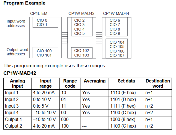
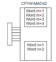
CP1W-MAD42
-
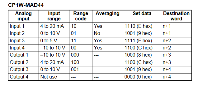
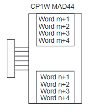
CP1W-MAD44
- Add Button
CP1W-MAD11 Range Code Example
- Input 1 = -10V to 10V
- Input 2 = 4 to 20mA
- Output 1 = 4 to 20mA
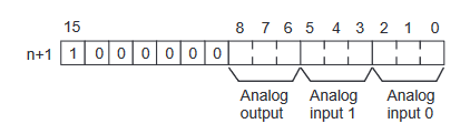
The below graphic shows how the range codes are structured
- Input 1 set data = Range Code (-10 to 10V, 000)
- Input 2 set data = Range Code (0 to 10V, 010)
- Output 1 set data = Range Code (4 to 20mA, 100)
Therefore the n+1 is:
| 15 | 14 | 13 | 12 | 11 | 10 | 9 | 8 | 7 | 6 | 5 | 4 | 3 | 2 | 1 | 0 | |
| n+1 | 1 | 0 | 0 | 0 | 0 | 0 | 0 | 1 | 0 | 0 | 0 | 1 | 0 | 0 | 0 | 0 |
CP1W-MAD44 Range Code Example
- Input 1 = -10V to 10V
- Input 2 = 0 to 10V
- Input 3 = 4 to 20mA
- Input 4 = Not in use
- Output 1 = -10V to 10V
- Output 2 = 0 to 10V
- Output 3 = 4 to 20mA
- Output 4 = Not in use
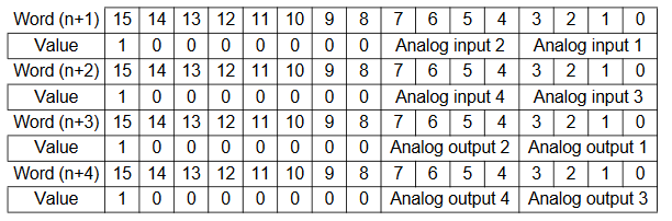
The below graphic shows how the range codes are structured for CP1W-MAD44
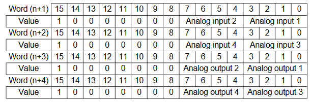

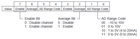
- Input 1 set data = Input Use(Yes, 1), Average(No, 0), Range Code (-10 to 10V, 00)
- Input 2 set data = Input Use(Yes, 1), Average(No, 0), Range Code (0 to 10V, 01)
- Input 3 set data = Input Use(Yes, 1), Average(No, 0), Range Code (4 to 20mA, 10)
- Input 4 set data = Input Use(No, 0), Average(No, 0), Range Code (N/A, 000)
- Output 1 set data = Output Use(Yes, 1), Range Code (-10 to 10V, 000)
- Output 2 set data = Output Use(Yes, 1), Range Code (0 to 10V, 001)
- Output 3 set data = Output Use(Yes, 1), Range Code (4 to 20mA, 100)
- Output 4 set data = Output Use(No, 0), Range Code (N/A, 000)
Therefore the n+1 to n+4 are:
| 15 | 14 | 13 | 12 | 11 | 10 | 9 | 8 | 7 | 6 | 5 | 4 | 3 | 2 | 1 | 0 | |
| n+1 | 1 | 0 | 0 | 0 | 0 | 0 | 0 | 0 | 1 | 0 | 0 | 1 | 1 | 0 | 0 | 0 |
| n+2 | 1 | 0 | 0 | 0 | 0 | 0 | 0 | 0 | 0 | 0 | 0 | 0 | 1 | 0 | 1 | 0 |
| n+3 | 1 | 0 | 0 | 0 | 0 | 0 | 0 | 0 | 1 | 0 | 0 | 1 | 1 | 0 | 0 | 0 |
| n+4 | 1 | 0 | 0 | 0 | 0 | 0 | 0 | 0 | 0 | 0 | 0 | 0 | 1 | 1 | 0 | 0 |
CP1W-MAD42 Range Code Example
- Input 1 = -10V to 10V
- Input 2 = 0 to 10V
- Input 3 = 4 to 20mA
- Input 4 = Not in use
- Output 1 = -10V to 10V
- Output 2 = Not in use
The below graphic shows how the range codes are structured for CP1W-MAD44
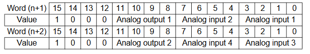
- Input 1 set data = Input Use(Yes, 1), Average(No, 0), Range Code (-10 to 10V, 00)
- Input 2 set data = Input Use(Yes, 1), Average(No, 0), Range Code (0 to 10V, 01)
- Input 3 set data = Input Use(Yes, 1), Average(No, 0), Range Code (4 to 20mA, 10)
- Input 4 set data = Input Use(No, 0), Average(No, 0), Range Code (N/A, 000)
- Output 1 set data = Output Use(Yes, 1), Range Code (-10 to 10V, 000)
- Output 2 set data = Output Use(No, 0), Range Code (N/A, 0)
Therefore the n+1 and n+2 are:
| 15 | 14 | 13 | 12 | 11 | 10 | 9 | 8 | 7 | 6 | 5 | 4 | 3 | 2 | 1 | 0 | |
| n+1 | 1 | 0 | 0 | 0 | 1 | 0 | 0 | 0 | 1 | 0 | 0 | 1 | 1 | 0 | 0 | 0 |
| n+2 | 1 | 0 | 0 | 0 | 0 | 0 | 0 | 0 | 0 | 0 | 0 | 0 | 1 | 0 | 1 | 0 |
Step 4
Write the range codes to the IO area to initialise the analogue input/output configuration. See Appendix A for information on how to determine the memory areas your expansion module is using. The below example goes over how to write the range codes to your expansion cards.
Programming Examples
-
Analog Input Module
-
Analogue Output Module
-
Analogue Input/Output Module
- Add Button
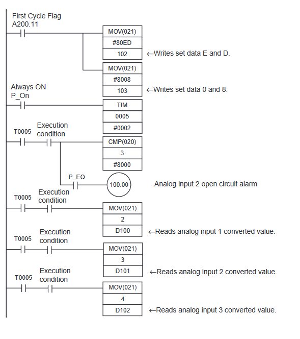
CP1W-AD041 Programming Example
Note that despite the expansion being an input, we are writing to the output area.
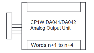
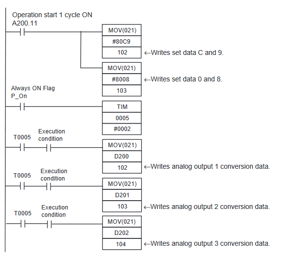
CP1W-DA041 Programming Example
Expansion Module Selection
-
CP1W-MAD11
-
CP1W-MAD42/44
- Add Button
CP1W-MAD11 Programming Example
| Analog In/Out | Range | Range code |
| Input 1 | 0 to 10V | 001 |
| Input 2 | 4 to 20mA | 010 |
| Output 1 | 0 to 10V | 001 |
| Set Data | 1000 000001010001 (Hex 8051) |
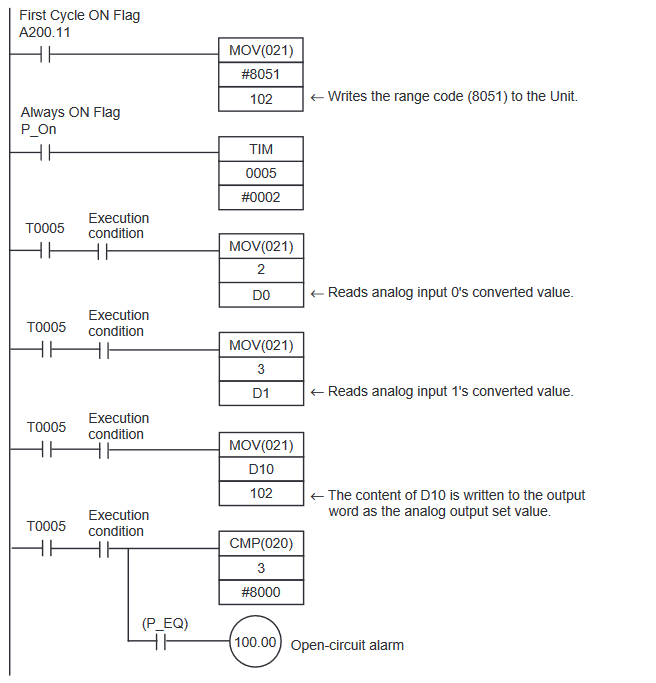
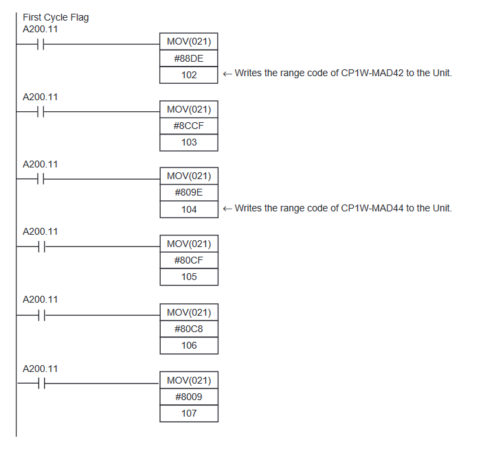
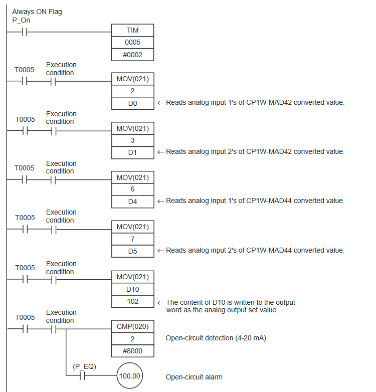
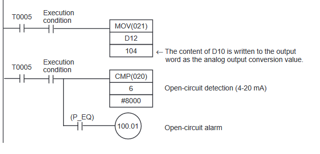
CP1W-MAD42/44 Programming Example
Note that despite the expansion being an input combination unit, we are writing exclusively to the output area.
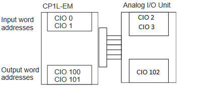
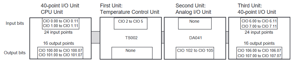
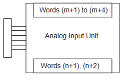
Appendix A - Analog Memory Areas
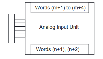
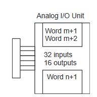
Expansion Units and Expansion I/O Units are allocated I/O bits in the order the Units are connected starting from the CPU Unit. When the power to the CPU Unit is turned ON, the CPU Unit checks for any Expansion Units and Expansion I/O Units connected to it and automatically allocates I/O bits. See example below for how memory is allocated to analog input and output areas.
Delete
Appendix B - Analog IO Specifications
Analog Inputs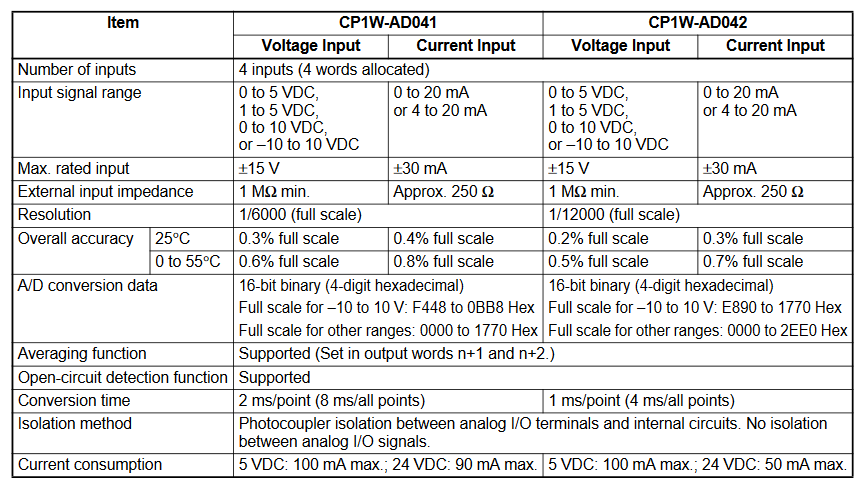 Analog Outputs
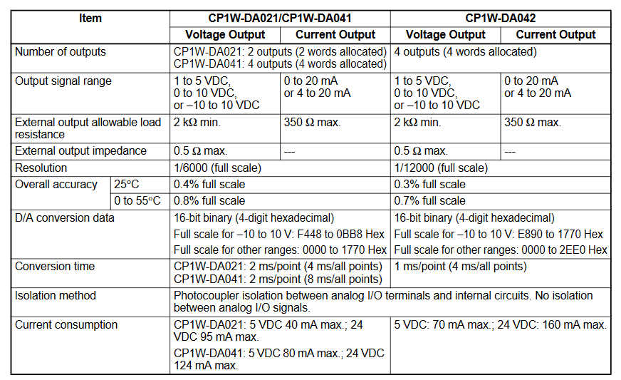
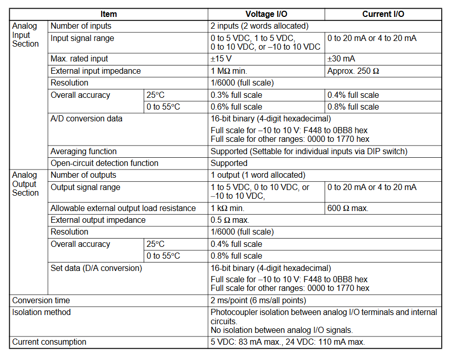
Analog In/Out MAD11
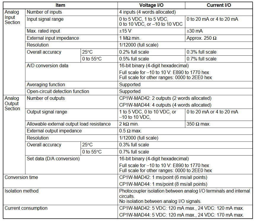
 Analog In/Out MAD42/44
Delete
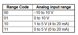
Appendix C - Analog Signal Ranges
-
CP1W-AD
-
CP1W-DA
-
CP1W-MAD
- Add Button
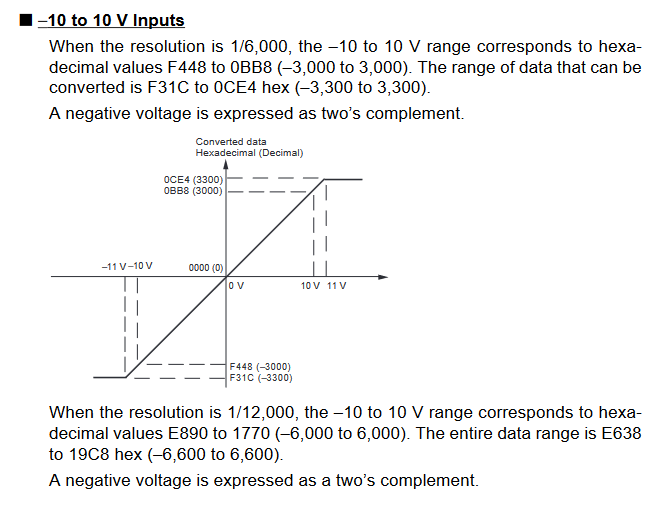
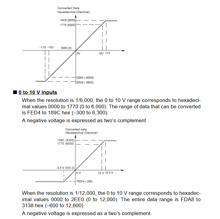
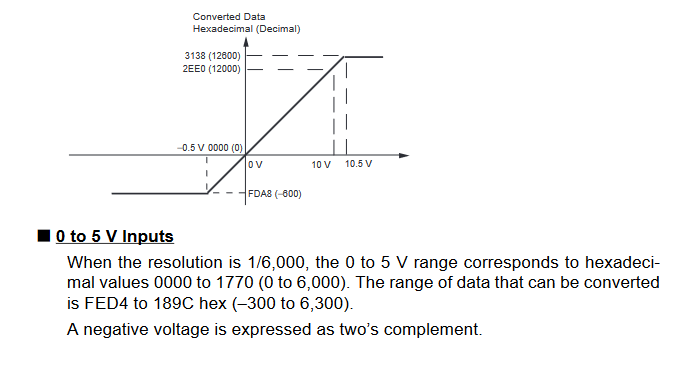
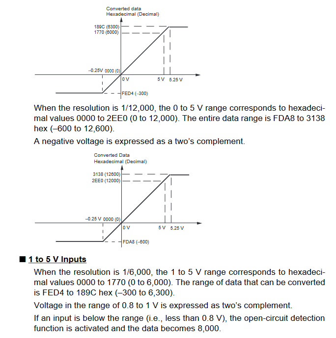
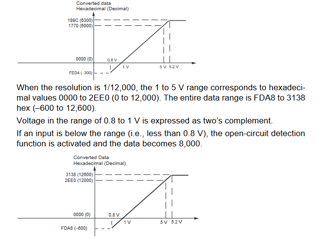
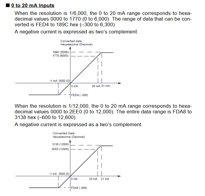
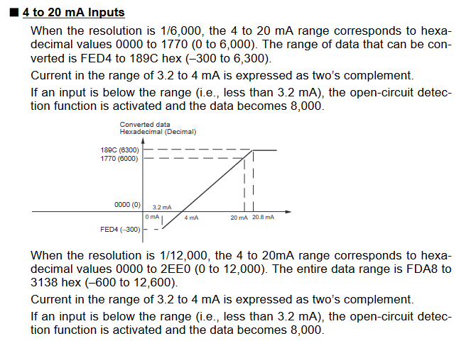
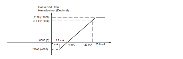
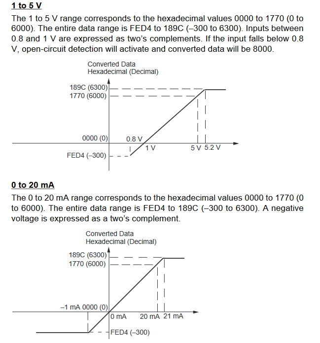
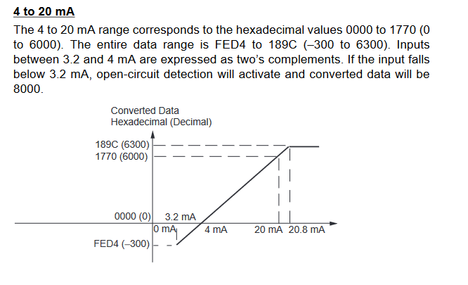
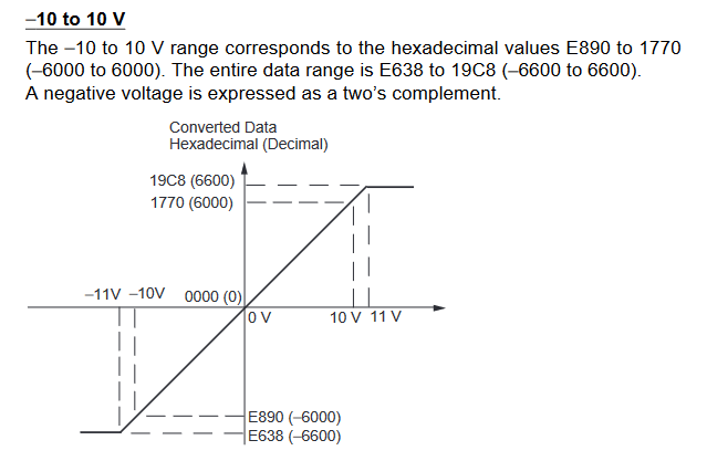
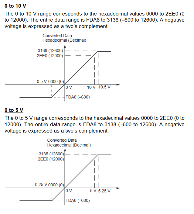
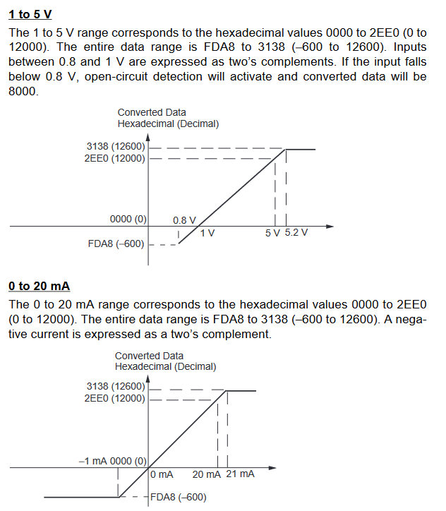
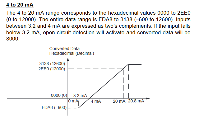
Input Signal Ranges
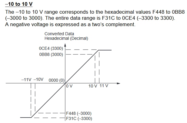
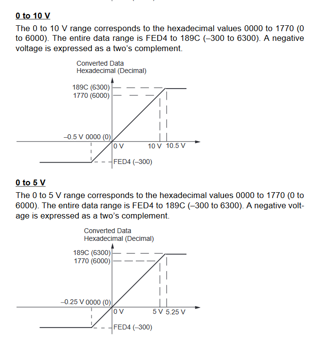
The vertical axis indicates the digital value in the expansion unit, and the horizontal axis indicates the true analog value.

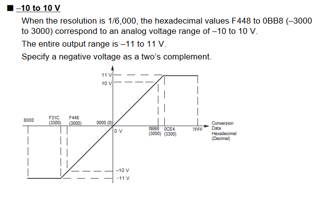
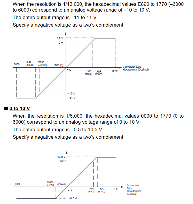
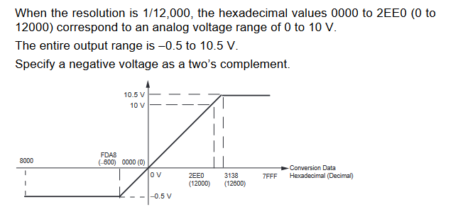
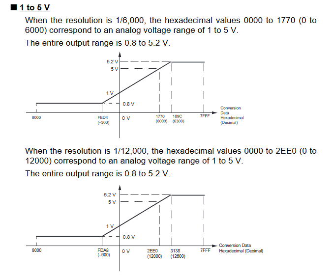
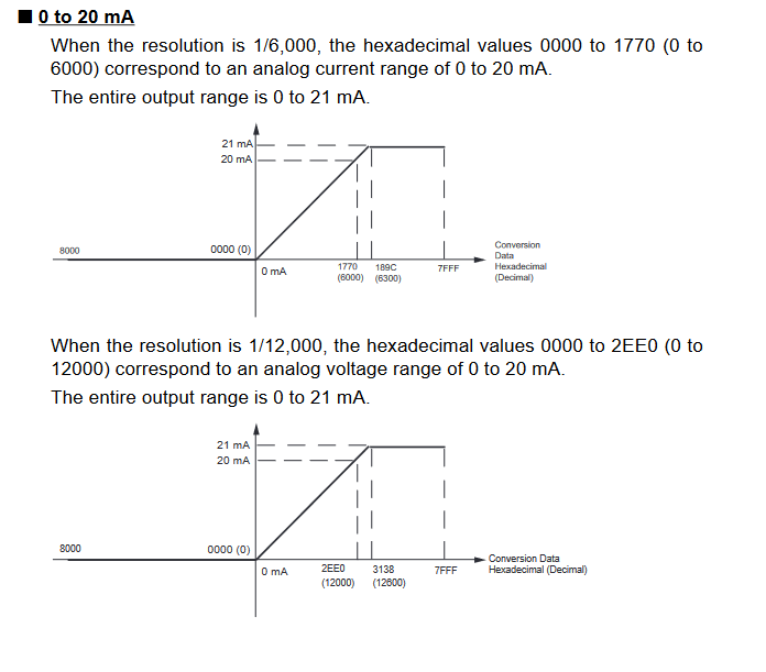
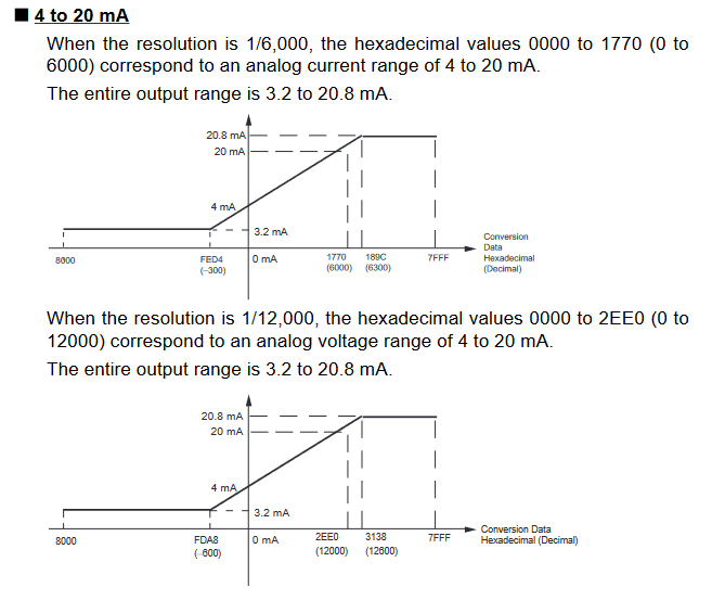
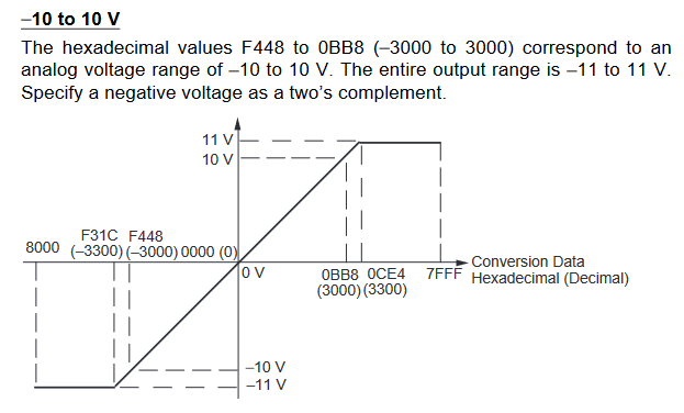
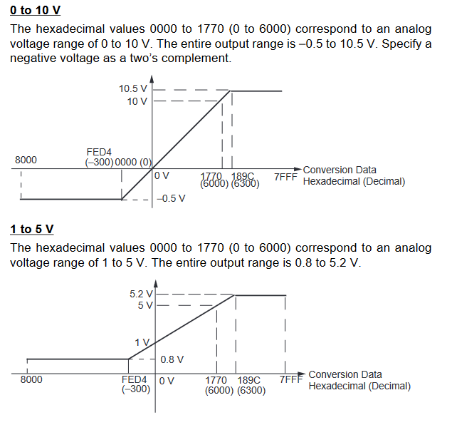
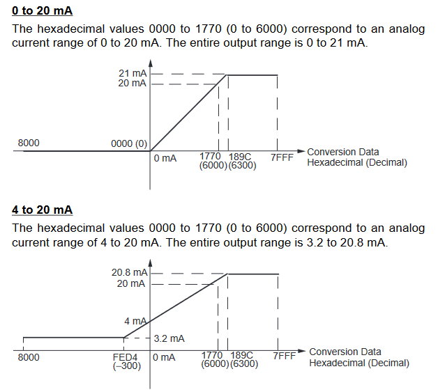
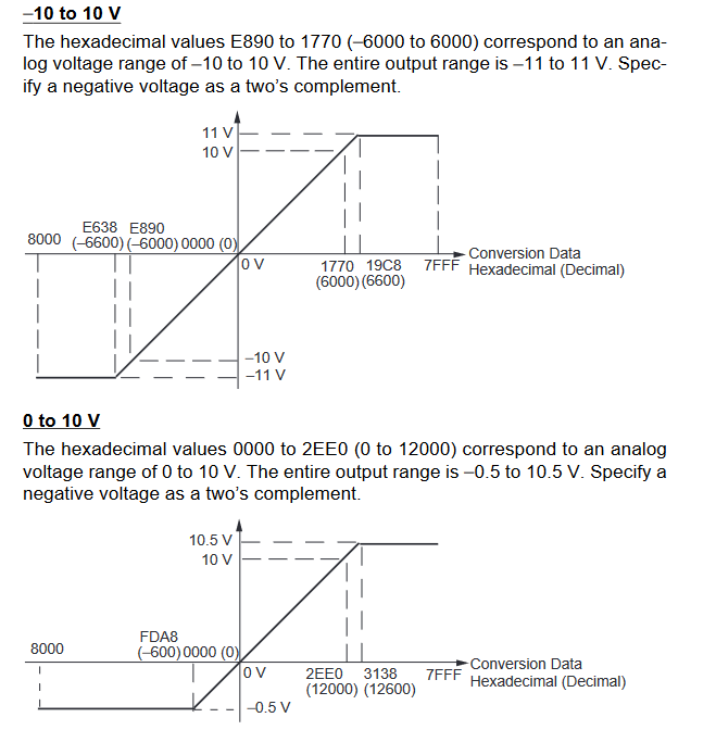
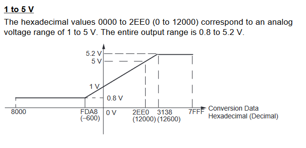
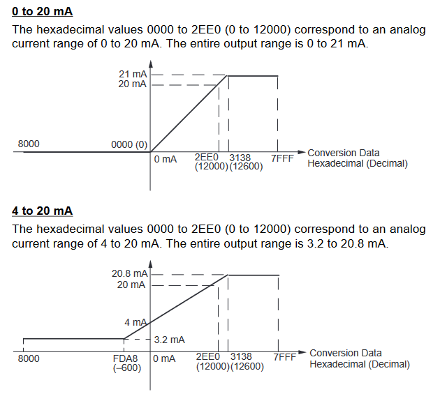
Output Signal Ranges
The vertical axis indicates the digital value in the expansion unit, and the horizontal axis indicates the true analogue value.
-
CP1W-MAD11
-
CP1W-MAD42/44
- Add Button
-
Inputs
-
Outputs
- Add Button
MAD11 Signal Ranges
MAD11 Signal Ranges
-
Inputs
-
Outputs
- Add Button
MAD42/44 Signal Ranges
MAD42/44 signal ranges
Appendix F - Analog Range Codes
-
Analogue Input module
-
Analogue Output module
-
Analog Input/Output module
- Add Button
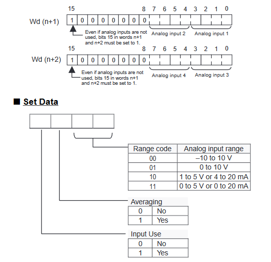
CP1W-AD041 Range codes
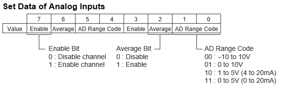
Write the settings for input use, averaging use, and range codes for words
n+1 and n+2.
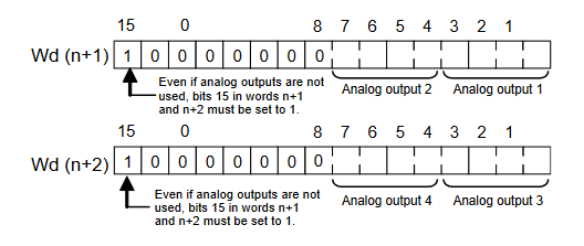
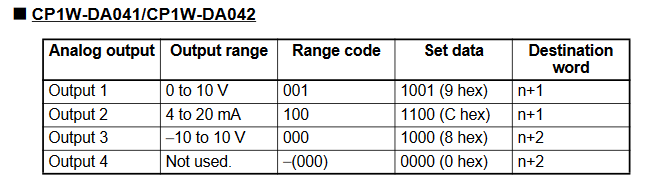
CP1W-DA41 Range Codes
Analogue Input/Output Module Range Codes
-
CP1W-MAD11
-
CP1W-MAD42
-
CP1W-MAD44
- Add Button
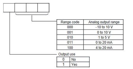
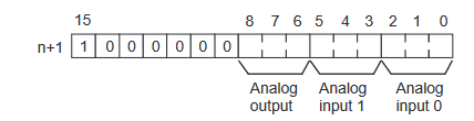
CP1W-MAD11 Range Codes
starting from the next word following the last word allocated to the CPU Unit
or previous Expansion Unit or Expansion I/O Unit.
CP1W-MAD42 Range Codes
starting from the next word following the last word allocated to the CPU Unit
or previous Expansion Unit or Expansion I/O Unit.
 Analogue input configuration data structure
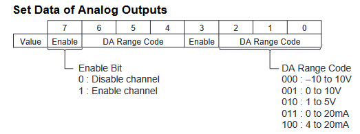
 Analogue output configuration data structure
CP1W-MAD44 Range Codes
starting from the next word following the last word allocated to the CPU Unit
or previous Expansion Unit or Expansion I/O Unit.
Analogue input configuration data structure
Analogue output configuration data structure