Introduction
This guide will show the process of connecting a CP1L or CP1H PLC to an NB HMI using a CP1W-EIP61 option board.
Normally the connection of a CP1L or CP1H to an HMI is documented assuming the use of an NS HMI, or a CP1W-CIF41 option board. Allowing the use of an NB HMI increases the versatility of the CP1L or CP1H range, and the use of the CP1W-EIP61 option board provides an alternative to the CP1W-CIF41 option board.
Required Equipment,
- CP1L or CP1H PLC
- NB HMI
- CP1W-EIP61 Option Board
- CX-Programmer Software
- NB-Designer Software
- Ethernet Cables
- USB Cable (Type A to Type B)
- PC/Laptop (For programming and configuring)
- Network Switching Hub (Optional)
Procedure
Step 1: Hardware Configuration
Install the CP1W-EIP61 Option Board,
Ensure that the CP1L or CP1H (referred to from here as the PLC) is powered down.
Remove the option board slot cover from the front of the PLC. This is done by firmly squeezing the lock levers on the cover and pulling it away from the PLC. Note that if the PLC has two option board slots, either may be used for this process.
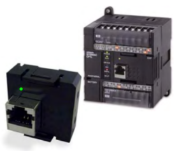
Insert the CP1W-EIP61 option board into the PLC. Ensure that the orientation of the option board is correct, with the indicator LED above the ethernet port, as shown in the below image. Firmly press the option board until it clicks into place.
Configure the PLC's DIP switches. These are located under a protective cover to the left side of the indicator lights on the PLC, and may differ in appearance and number depending on the exact PLC. In general, there will be either four or six DIP switches, as shown in the below two images.
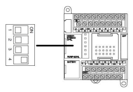
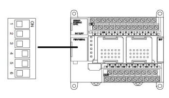
Note that the main difference between these two is the number of option board slot.
If you have mounted the CP1W-EIP61 option board in the first (leftmost) slot, set DIP switch 4 to the ON position.
If you have mounted the CP1W-EIP61 option board in the second (rightmost) slot, set DIP switch 5 to the ON position.
Network Connection,
Connect the CP1W-EIP61 to the NB HMI using an ethernet cable. This can be done directly, or through the use of a switching hub.
Step 2: Software Configuration
Determine the IP Addresses,
By default, the IP address of a CP1W-EIP61 option board is 192.168.250.11, with a subnet mask of 255.255.255.0. If the option board is directly connected to the NB HMI using ethernet, unplug the cable from the HMI and insert it into the ethernet port of your PC/laptop. If the option board is connected to the NB HMI through a switching hub, connect your PC/laptop to the switching hub via ethernet cable.
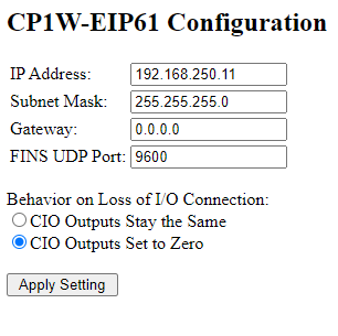
Once connected, open an internet browser application and enter '192.168.250.11' without the quotation marks into the URL search bar. This will present the page in the below image.
If the Configuration Page did not appear
If the above configuration page did not appear, and the ethernet cables are firmly connected, it is likely that the IP address of the CP1W-EIP61 has been changed from the default value.
In order to recover the IP address, connect your PC/laptop to the PLC using the USB cable. Open CX-Programmer, and go online with the PLC in monitoring mode.
Inspect the data memory areas of the PLC at D1200 and D1201. These memory addresses store the IP address octets in hexadecimal, with the following format.
D1200: The first and second octets of the IP address.
D1201: The third and fourth octets of the IP address.
For example, if D1200 = C0A8 and D1201 = FA11, the IP address is 192.168.250.11
Once the IP address is determined, open an internet browser as above and enter the IP address in the URL search bar. This will present the Configuration page for the CP1W-EIP61.
DeleteConfirm that the settings on this page are appropriate to your network. The IP address and other settings of the CP1W-EIP61 option board can be changed in this page, but care should be taken to ensure that the option board remains on the same subnet as the NB HMI.
Once any alterations have been made, the PC/laptop can be disconnected from the CP1W-EIP61. If the option board was previously directly connected to the NB HMI via the ethernet cable, reconnect this cable to the NB HMI.
The default IP address of an NB HMI is 192.168.250.1, with a subnet mask of 255.255.255.0. This can be confirmed by two methods.
Confirm IP Address on the HMI
Ensure that the NB HMI is powered down.
Set both DIP switches 1 and 2 on the rear of the HMI to ON.
Power the NB HMI back on. The HMI should now be in System Settings mode, which will enable you to check, confirm and modify the IP Address of the NB HMI.
Power off the NB HMI, reset DIP switches 1 and 2 back to OFF. Power on the NB HMI.
Confirm IP Address using NB-Designer
Connect your PC/laptop to the NB HMI using the USB cable.
Open Window's Device Manager to ensure that the USB driver for the NB HMI is properly installed. If it is not, a device should have appeared in Device Manager with a yellow warning or caution symbol. If this has occurred, install the USB driver, which is located by default at C:\Program Files (x86)\OMRON\NB-Designer\driver.
Open NB-Designer, then navigate to the Tools menu at the top of the screen, then System Manager.
In Communication Setting, click Set, select USB Port as the Communication Method, then click OK, as shown in the below image
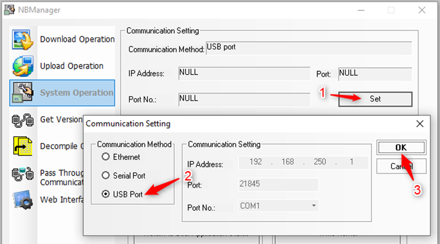
This will allow you to view the current IP address. If the IP address requires alteration, use the Set IP Address/Port options on this System Operation dialogue.
Establish the Network Connection,
This process assumes that a new project is being created on the NB HMI. If attempting to connect an existing NB HMI project to the PLC, refer to the note at the end of this section.
If the NB HMI was not already connected to your PC/laptop using the USB cable, connect it now, and open NB-Designer with a new project.
Using the Project Library Window on the left side of the NB-Designer window, add the correct model of NB HMI to the project. This must match the physical NB HMI's model number.
Using the same Project Library Window, add an 'OMRON CP Series Ethernet (UDP Slave)' PLC to the project. Double-click on the added PLC and ensure that the Network Port Setting is correctly set (by default, the IP address is 192.168.250.11 and the Port Number is 9600).
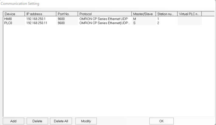
Using the same Project Library Window once more, add an Ethernet connector to the project. This will bring up a Communication Setting window. On this window, add the NB HMI and PLC, ensuring that the proper IP addresses are used. In addition, when adding the NB HMI, ensure that the Comm Protocol selected is 'OMRON CP Series Ethernet UDP'.
Once the Ethernet connector has been properly configured, the window should appear similar to the below image, though the device names may differ.
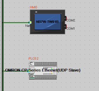
Click 'OK'. The main window of NB-Designer will show a configuration similar to the below image.
Press ctrl+D or use the Download option under the Tools menu to send this information to the NB HMI.
Note on Existing Projects
If the connection is being attempted using an existing NB-Designer project, the process is similar.
Before making any configuration changes, ensure that the NB-Designer project is current to the project loaded on the HMI, and maintain a backup of the project.
Instead of adding new devices, double-click on existing devices to reconfigure them if necessary, and only add devices that are actually new.
If the previous configuration used a different ethernet connection method than the CP1W-EIP61 option board, the PLC may need to be replaced in NB-Designer with the correct PLC. Please check if the existing PLC in the project is an 'OMRON CP Series Ethernet (UDP Slave)' PLC. If not, replace it with the appropriate PLC, ensuring that the name of the PLC is retained.
DeleteStep 3: Well done!
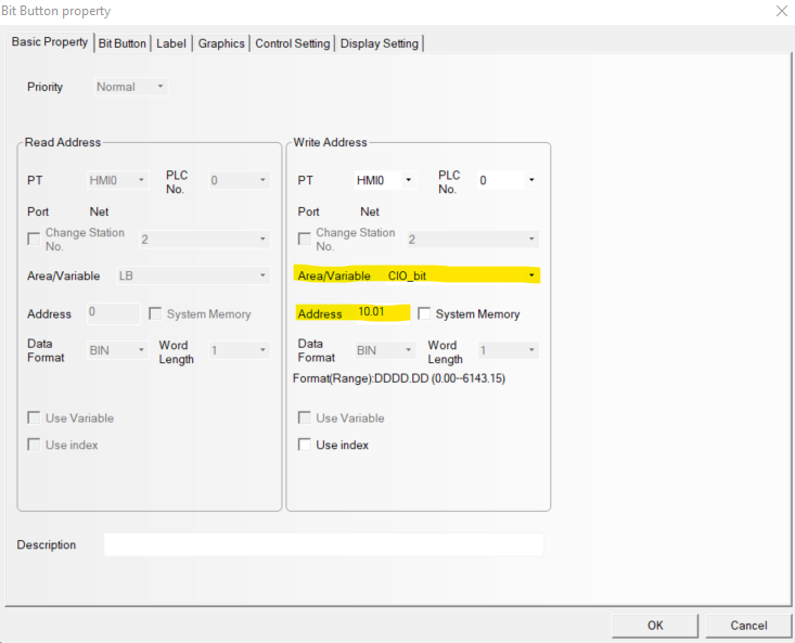
At this point, the PLC and NB HMI are connected and able to communicate with each other. This will work by the NB HMI being able to directly read and write from the memory areas on the PLC. This can be tested by adding a button or indicator to a screen, assigning it an area/variable associated with the PLC memory, downloading the project to the NB HMI, and then monitoring the PLC's memory while the button is actuated.
See the below image for an example of a Bit Button configured to access the PLC's CIO memory (specifically memory address 10.01)