Introduction
This guide is a step-by-step process of connecting an NJ or NX PLC and a Microscan Camera. For this guide, an MV40 camera was used, though all Microscan cameras can be connected with this method.
Pre-Requisites
Knowledge of Sysmac Studio.
Knowledge of basic operation of AutoVISION.
Required Hardware
NJ/NX PLC and Power Supply
Microscan device
Ethernet Switch or Router
Personal Computer (for programming)
Ethernet Cables
Procedure
Step 1 - Physical Setup
Connect the NJ/NX PLC and the Microscan Camera to the ethernet switch. Additionally, connect the programming computer to the same ethernet switch.
Step 2 - Sysmac Studio: Adding the Camera
Open Sysmac Studio and establish a connection to the PLC. Due to the network configuration, this should be performed by selecting to connect using 'Connect to Device', then 'Ethernet Connection via a hub'. It is required to enter the PLC's IP address for this connection method.
Once the connection is established, navigate to the Tools menu at the top of the screen, and select 'Ethernet/IP Settings'. This opens the Ethernet/IP Device List page. On this page, double-click on the PLC listed, or right-click and select 'Edit'. This will open the Built-In Ethernet/IP Port Settings Connection Settings page.
At this point, the EDS file for the Microscan Camera is necessary. These can be located here.
Right-click in the Toolbox, located in the upper-right section of the screen, directly beneath 'Target Device'. Select 'Display EDS Library', which will present the following pop-up window.
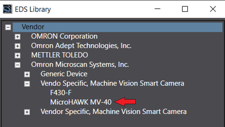
In this window, click the 'Install' button, browse to the EDS file for the Microscan Camera used, select it, and click 'Open'. This will add the Microscan Camera to the EDS library. Close the EDS window.
In the Toolbox at the top-right of the screen, click on the 'plus' button to add the device. In the window that appears, enter the IP address of the Microscan Camera, select the camera model from the list of models, and select the appropriate revision. In the example of the Microscan MV40, the model selected is 'MicroHAWK MV40', and the revision is '1'. Click 'add' to finish adding the device from the list.
Once added, the device should appear in the Toolbox.
Step 3 - Sysmac Studio: Communications
In the main window of Sysmac Studio, ensure that the Built-In Ethernet/IP Port Settings Connection Settings page is visible. On the left side of this page, there are navigation buttons. Select the button indicated in the below image to navigate to 'Connection'.
Once the Connection page is displayed, drag and drop the newly added device from the Toolbox in the upper-right of the main window, into the area directly below 'Target Device'. This will add the MV40 to the connection list, as shown in the below image.
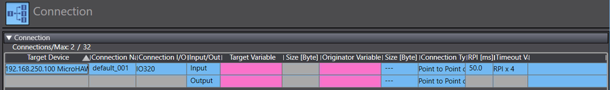
In the above image, the pink fields represent incomplete information required for the program to function. For the pink fields under 'Target Variable', the instance numbers for the device should be entered. Check the documentation of the EDS files, or the files themselves, to determine the appropriate Input and Output Target Variable. In the example of the MV40, the Input Target Variable is '102', while the Output Target Variable is '114'.
Once these values are entered, the Size [Byte] of both the Input and Output should autofill to 320 bytes (for the MV40). If this does not autofill, check the EDS documentation for the instance variables.
The pink fields under 'Originator Variable' must also be filled. In order to accomplish this, new data structures and global variables must be created.
Using the Multiview Explorer on the left side of the screen, navigate to Programming, then Data, then Data Types. Selecting Data Types will show the screen from the below image.
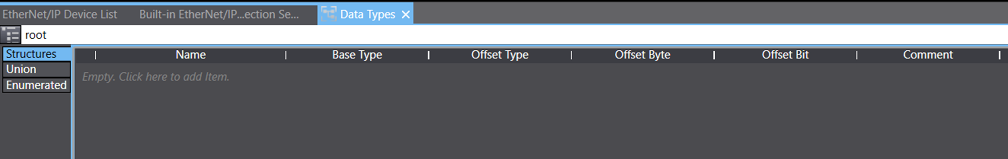
Ensure that 'Structures' is selected on the left side, before right-clicking in the empty section and selecting 'Create New Data Type'. A name is required for this data type, which can be arbitrary. For this process, 'OUTPUT_STRUCTURE' is used.
Right-click on this table again, and select 'Create New Member'. This generates a new member element of the data structure. Name this member, and provide it with a data type. Repeat this, until the data structure is populated, and identical to the data structure in the below image. The contents of the image are also provided in a table beneath it.
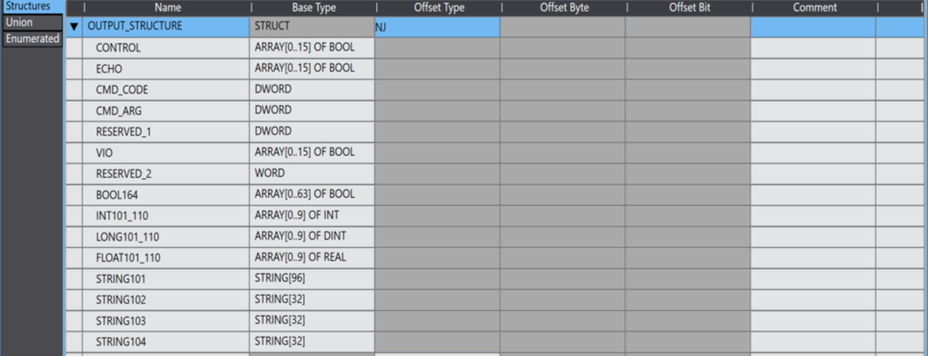
Output Data Structure Members
| Member Name | Member Variable Type |
| CONTROL | ARRAY[0..15] OF BOOL |
| ECHO | ARRAY[0..15] OF BOOL |
| CMD_CODE | DWORD |
| CMD_ARG | DWORD |
| RESERVED_1 | DWORD |
| VIO | ARRAY[0..15] OF BOOL |
| RESERVED_2 | WORD |
| BOOL164 | ARRAY[0..63] OF BOOL |
| INT101_110 | ARRAY[0..9] OF INT |
| LONG101_110 | ARRAY[0..9] OF DINT |
| FLOAT101_110 | ARRAY[0..9] OF REAL |
| STRING101 | STRING[96] |
| STRING102 | STRING[32] |
| STRING103 | STRING[32] |
| STRING104 | STRING[32] |
Note that identical means that the variable names and types must be exactly the same as in the above image.
Repeat the process of created a data structure and populating it for the input data structure. For this process, the data structure name is 'INPUT_STRUCTURE'. Ensure that the populated data structure is identical to the image below. The contents of the image are also provided in a table beneath it.
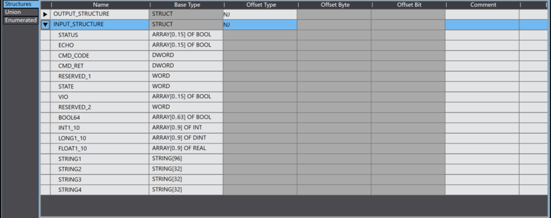
Input Data Structure Members
| Member Name | Member Variable Type |
| STATUS | ARRAY[0..15] OF BOOL |
| ECHO | ARRAY[0..15] OF BOOL |
| CMD_CODE | DWORD |
| CMD_RET | DWORD |
| RESERVED_1 | WORD |
| STATE | WORD |
| VIO | ARRAY[0..15] OF BOOL |
| RESERVED_2 | WORD |
| BOOL64 | ARRAY[0..63] OF BOOL |
| INT1_10 | ARRAY[0..9] OF INT |
| LONG1_10 | ARRAY[0..9] OF DINT |
| FLOAT1_10 | ARRAY[0..9] OF REAL |
| STRING1 | STRING[96] |
| STRING2 | STRING[32] |
| STRING3 | STRING[32] |
| STRING4 | STRING[32] |
Once the data structures have been created and populated, use the Multiview Explorer to navigate to Programming, then Data, then Global Variables. Select Global Variables to show the table of existing Global Variables in the program.
Right-click on this table, and select 'Create New'. Repeat this, such that there are two new Global Variables in the table.
Name these two variables appropriately, and ensure that one is of the data type of the input data structure ('INPUT_STRUCTURE' in this process), and the other is of the data type of the output data structure ('OUTPUT_STRUCTURE' in this process). For these variables, ensure that under the 'Network Publish' heading of the table, the input variable is set to 'Input', and the output variable is set to 'Output'.
The names of these two variables can be arbitrary. This process uses 'MV40_OUT' and 'MV40_IN' for the output and input respectively.
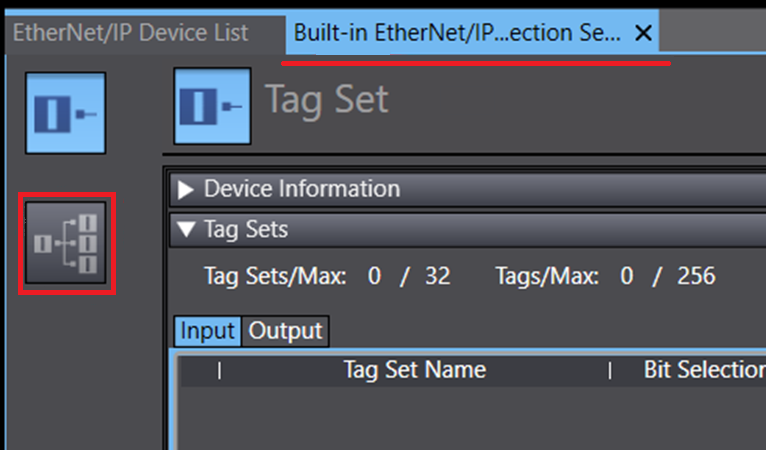
With the global variables created and configured, return to the Built-In Ethernet/IP Port Settings Connection Settings page, and use the navigation buttons on the left of that page to ensure that the 'Tag Set' page is active.
On this page, click on the button labelled 'Registration All', located in the upper-right. This will cause the program to ask for confirmation. In this confirmation window, ensure that the two global variables previously created are listed under Input and Output as appropriate, then click 'Register'. This will create the tag sets for the connection, as shown in the below two images. Note that Inputs are distinct from Outputs.
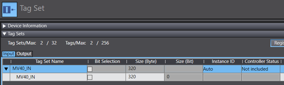
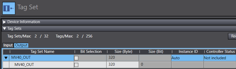
Now that the tag sets are created, use the navigation buttons on the side of the Built-In Ethernet/IP Port Settings Connection Settings page to return to the Connection page. Now, select the appropriate variables under Originator Variables, such that the input variable is assigned to the input line, and the output variable is assigned to the output line.
Ensure that the two Size (Byte) columns have matching values.
Now, the connection settings on Sysmac Studio are complete. Transfer them to the PLC by using the 'Transfer to PLC' button, located in the lower right of the Built-In Ethernet/IP Port Settings Connection Settings page. Note that this must be done in this manner, as the Ethernet/IP settings will not be transferred in the normal manner of transferring a program to the PLC.
The data structures and tag links can be seen in the following example, which shows the settings to connect an NX1P2 PLC to a Microscan MV-40.
NX1P2 to Microscan Example.smc2
Step 4 - AutoVISION Connection
Run the AutoVISION software on the PC.
Once the software is running, select the camera under the 'Connect' heading on the screen.
If the PC cannot connect to the camera, see this article for resolutions to this issue.
Step 5 - AutoVISION Data Linking
In order to set up Data Linking, once the camera is connected, acquire an image and create a job as per normal operation of the camera.
To add a Data Link, which enables information to be sent to the PLC, select a link icon from the desired job element, as shown in the below image.
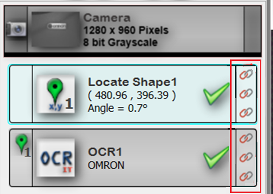
Note that different link icons in the same job element will convey different information to the PLC about that job element.
Clicking on these Data Link icons will open a dialogue window, where the style of the link and the involved variable may be selected. For example, using the top Data Link icon in the Locate Shape1 job element from the previous picture and selecting 'EIP IN' link to 'bool1' will send the job element state (Good or Not Good) to the variable of bool1.
Once a Data Link has been established, the background of the link icon will be green.
Step 6 - AutoVISION Camera Triggering
To enable the camera's image capture to be triggered from the PLC, click on the 'Camera' section of the processing flow. This can be seen on the top of the previous image.
This will cause the right side of the AutoVISION window to show camera details. In this section, click on the 'Trigger' section and change the Trigger Type to 'Virtual'.
Once this is done, the camera will capture an image when the boolean value of the eighth bit of the CONTROL member of the output global variable on the PLC becomes high. For example, in this process, this would be the value of MV40_OUT.CONTROL[8].