Introduction
In the CP series (CP2E, CP1H & CP1L) units are added to the CPU unit and cascade to the right in a daisy chain manner. It is straightforward to determine the words which are assigned to the inputs and/or outputs for each module.
More information
This information is covered in detail in the CPU operation manuals, typically section 9 "Using Expansion Units and Expansion I/O" discuss this feature. For instance you can refer to the manual W516-E1.04.pdf which is for the CP1L-E (built in ethernet models) or higher revision to get more information.
Note: CP1 series information is contained in a single manual, typically titled Operation Manual. However newer manual releases (such as the CP2E) have divided into Hardware and Software manuals. This information is covered by the Software manual in such separated manuals.
The method of addressing is common to all mentioned units, however the number of units that are able to be added may vary by CPU IO size on CP1L (max 3 units for 30 IO and higher) and CP1H (7 units max). Note a maximum IO word allowance applies to both series in addition to the max units, so the limiting factor is which limit is reached first.
Note that CPM1A-xxxx expansion units are compatible with the CP series, so upgrades of the CPU from CPM1A series to CP1 series can reuse the expansion IO units. However these units are discontinued and a full upgrade to current generation is generally recommended for simplicity of maintenance.
"Channels" and "Words" are the same thing, both are a 16 bit wide memory register. The two terms can be used interchangeably within OMRON C series devices.
Method
Determine the consumed words on the CPU unit. The CPU has both built in Inputs and Outputs. These start at word 0 for inputs, and word 100 for outputs. On the PLC you can see the print 0CH for the first bank of inputs, and 100CH on the first bank of outputs. You may also see 1CH and 101CH (and higher for 60 IO units). The highest of these channels or words, is the last consumed words for the built in inputs or outputs. Note the terminal information which includes these designations is shows in the manual section 2-2-3 - I/O Specifications. In the manual the prefix CIO is used, this is Core IO and can be read the same as word or channel.
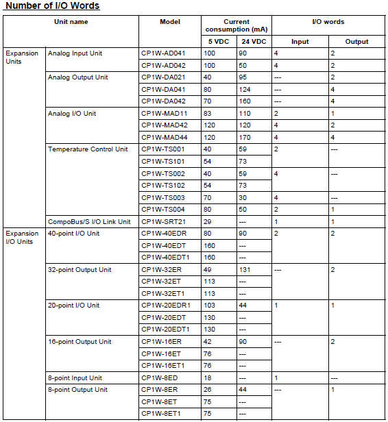
The below table is located in section 9-1 and gives the number of input and output words for the expansion unit of interest. Note the number of input and output words for your units. Also decide on the order you will connect the expansion units to your CPU as these two factors, in addition to the first available words, will determine the mapped words.
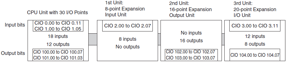
Expansion Units and Expansion I/O Units are allocated I/O bits in the order the Units are connected starting from the CPU Unit. When the power to the CPU Unit is turned ON, the CPU Unit checks for any Expansion Units and Expansion I/O Units connected to it and automatically allocates I/O bits. Note the below diagram which has examples of the allocated words. If a unit does not contain inputs or outputs, no words are allocated.
Note that an analog Input unit gets output words assigned, this is a detail that is sometimes missed. The output words are used on the first program scan to configure the types of the inputs, ie the Analog Range codes are written (MOVed) to these words using the P_First_Cycle flag.
The Analog output units only have allocated output words, the first two words that are used for the writing of the analog conversion values are also used once on the P_First_Cycle flag to write their analog range codes. After the first scan of the PLC, the output values can be moved to the words instead of the range codes.
This example shows the input or output words increasing as the previous unit consumes them. This is a "Next Available" addressing scheme. It makes no difference what the type of units are, only the number of words each unit will need to consume. Also note that a fresh word is allocated each time, even if the full 16 bits in each word are not consumed, as shown by the second module, being an 8 bit input unit.