Introduction
The purpose of this document is to demonstrate the process of setting up an Ethernet/IP network using two master PLC's via Network Configurator.
Configuration
The following configuration was used:

Procedure
Step 1 - Configuring the IP Address of the PC
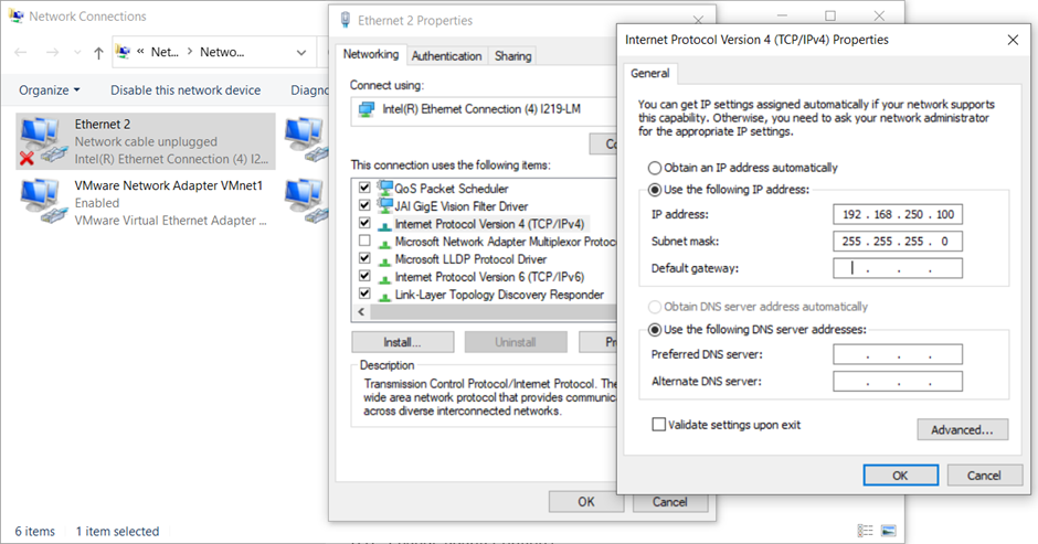
1. Change the IP address of the Ethernet port on the PC to the same subnet as the PLCs used.
As seen above, the CJ2M has an IP Address of 192.168.250.1 and the NJ101 has an IP address of 192.168.250.41. Both of them have a subnet of 192.168.250.xx. The configuration can be done by following the address: Control Panel\Network and Internet\Network Connections. Select the corresponding Ethernet port and select "Internet Protocol Version 4 (TCP/IPv4)". Change the IP address so that it has the format of 192.168.250.xx where xx can be any number that is not 1 or 41. 100 was used below.
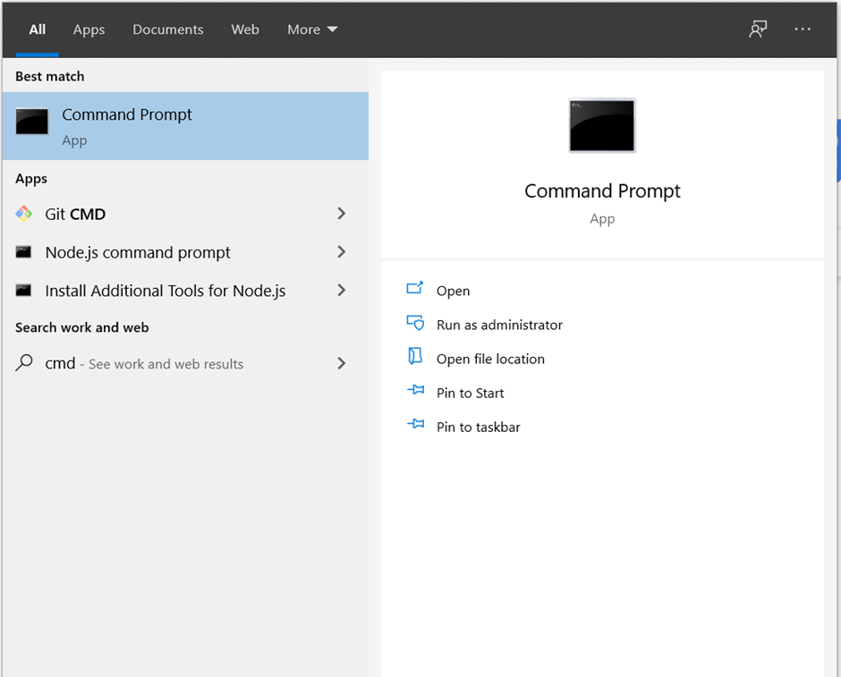
2. Next, check if the PLCs are showing up on the Network by going to the Command prompt.
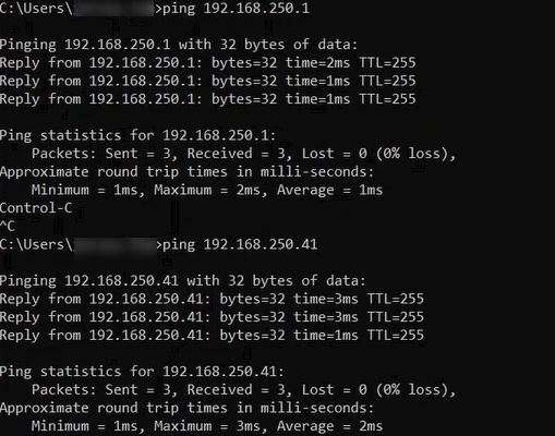
3. Type in the command "ping 192.168.250.1" to see if the PC can detect the CJ2M through the Ethernet Port. The following shows the result where both the PLCs were present on the Network. Do this also for the NJ system on "192.168.250.41".
Step 2 - Starting Network Configurator
1. Find Network Configurator by going to the search tab.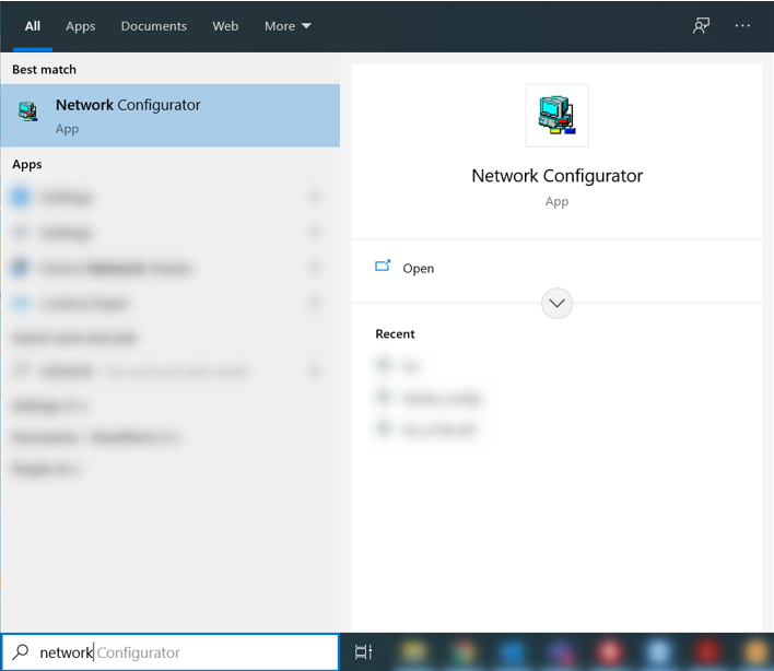
If Network Configurator does not show up through the search bar, Network Configurator can also be found under the address: C:\Program Files (x86)\OMRON\CX-One\Network Configurator\Program\NetConfigurator
2. The program should show up as below.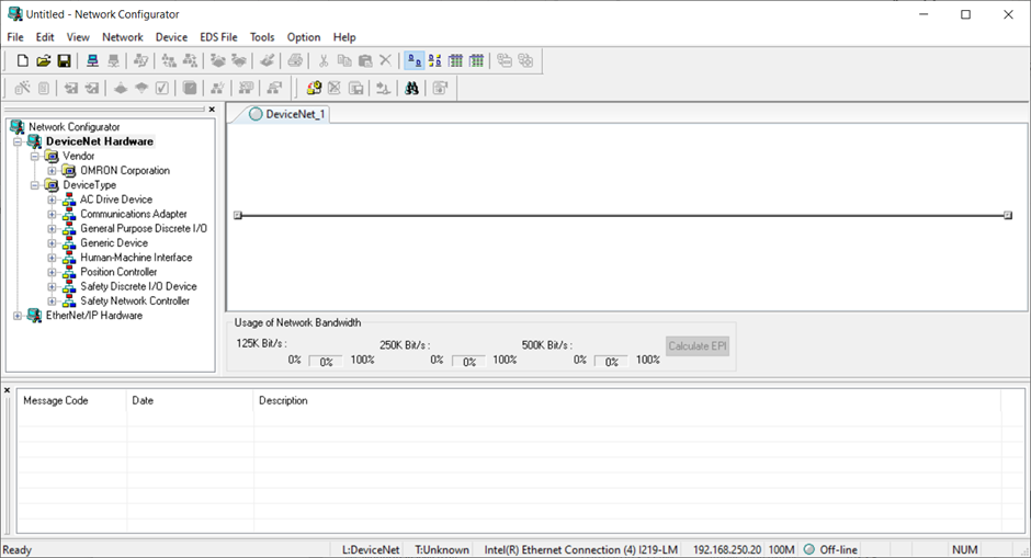
Step 3 - Configuration and Connection
1. Go into Option -> Select Interface -> Ethernet I/F for the configuration through Ethernet Connection.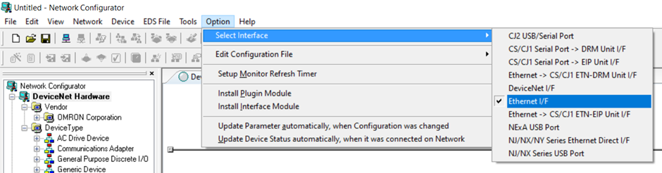
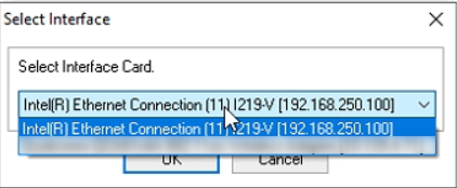
Select the corresponding Ethernet port defined earlier.
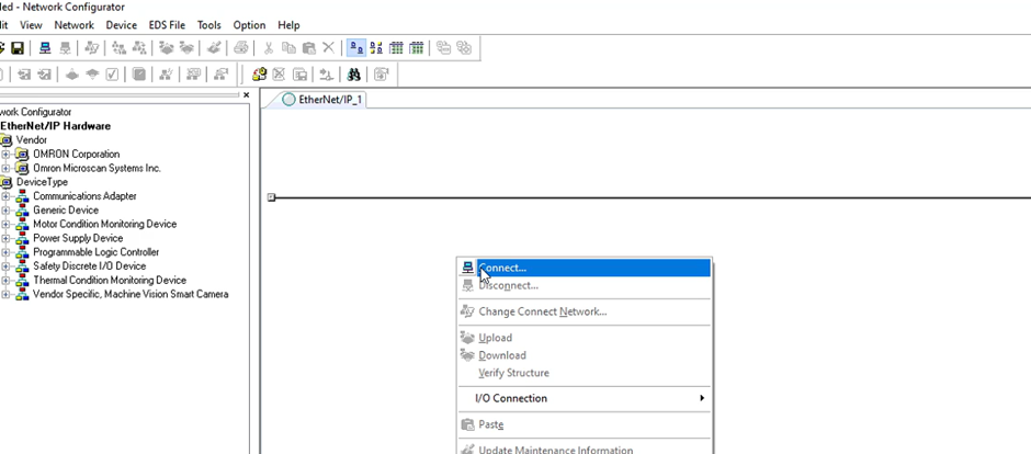
3. The PLCs will show up on the network.
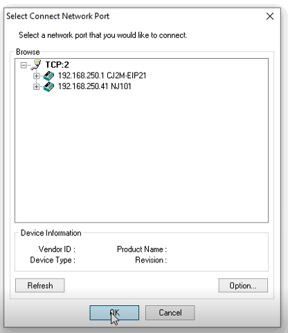
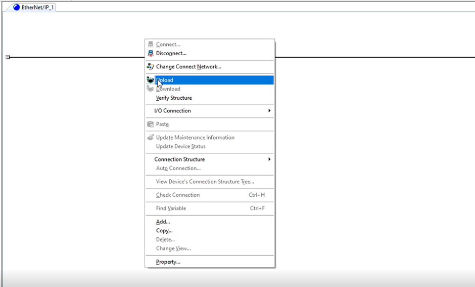
4. Do an upload from the network.
5. The corresponding devices will be shown on the interface: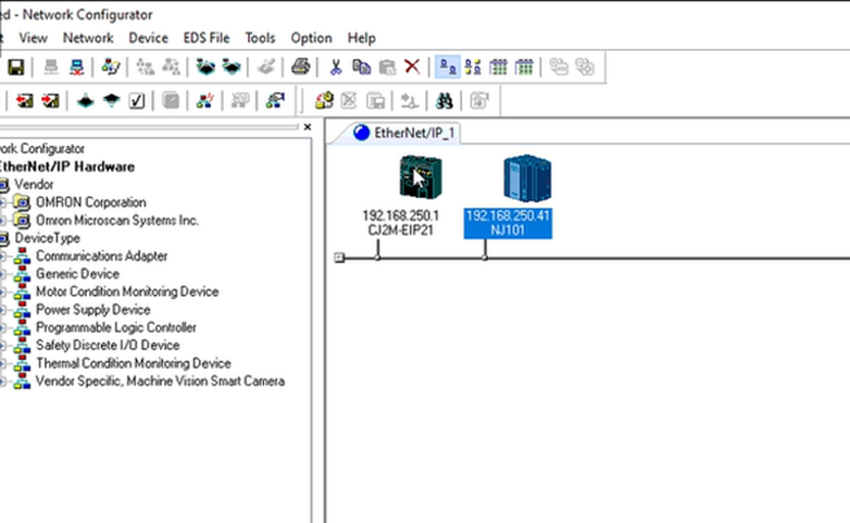
Step 4 - Configuration of Tag Sets
Every device will have either an input tag, output tag or both. In this case, both the PLCs will be transmitting data to each other so they will both have an input tag and an output tag.
1. Configure the tag sets by double clicking on the device. Click on Edit Tags (Highlighted in yellow) to configure the naming and size of each tag sets. 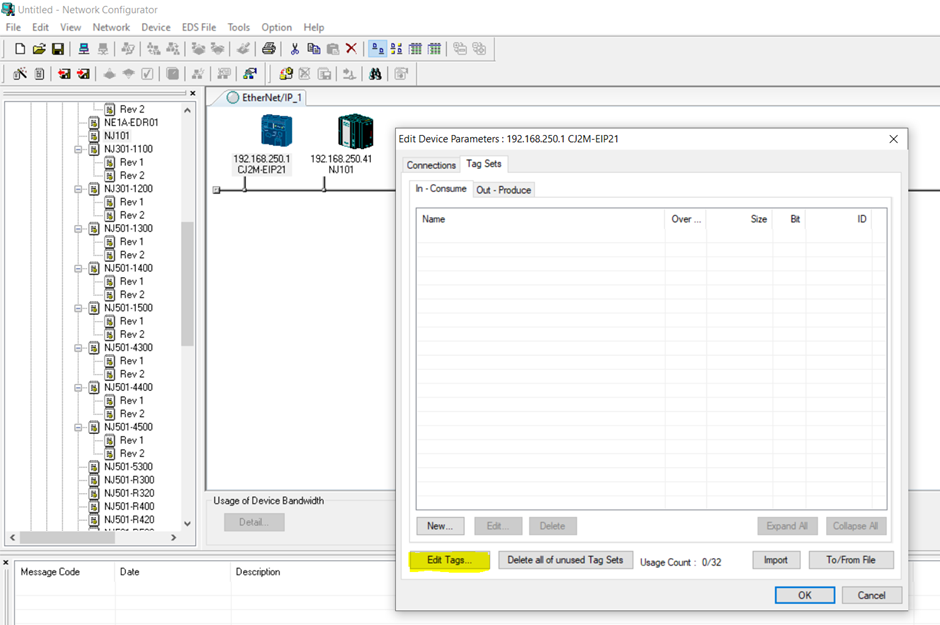
2. Click on New (as highlighted) and configure the tag as below. D200 is a memory area in the CJ so the input data would be directly transmitted into the D200 area.
3. Define the size of data being transmitted into this tag set. In this case, 16 bytes was defined. Each variable types has their corresponding size. Refer to this link for more information: https://www.myomron.com/index.php?action=kb&article=1628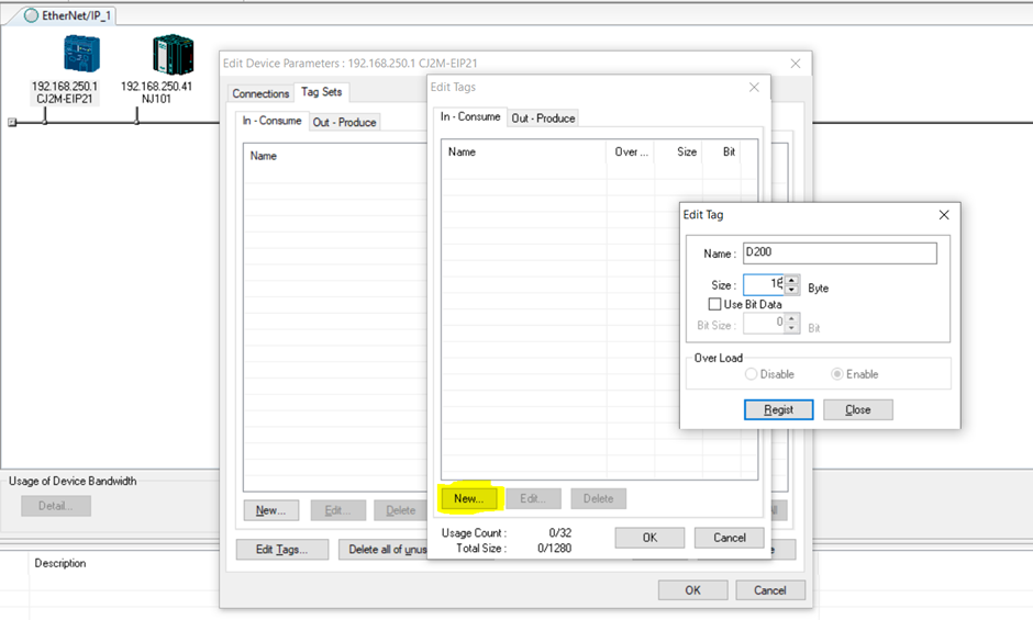
4. Do the same for the output tag sets. Click on the Out-Produce tag as shown and create a new tag set by clicking on the New button as well. D300 and 16 bytes was used in this demo.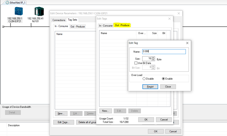
5. Once OK is clicked, the configured tag sets will show up under the “Edit Device Parameters” window.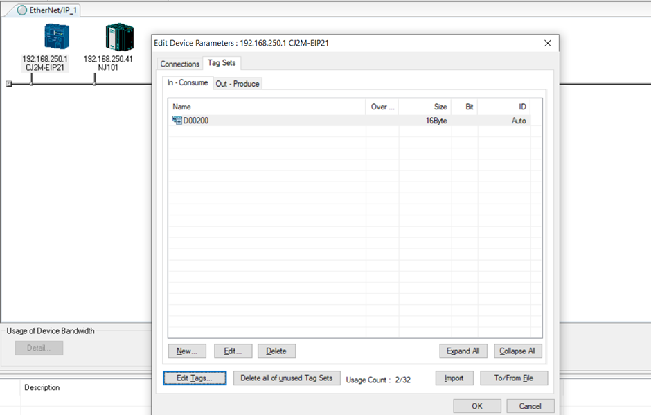
The input and output tag sets does not necessarily have to be the same size. Certain devices have limitations on how many tag sets it is able to work with.
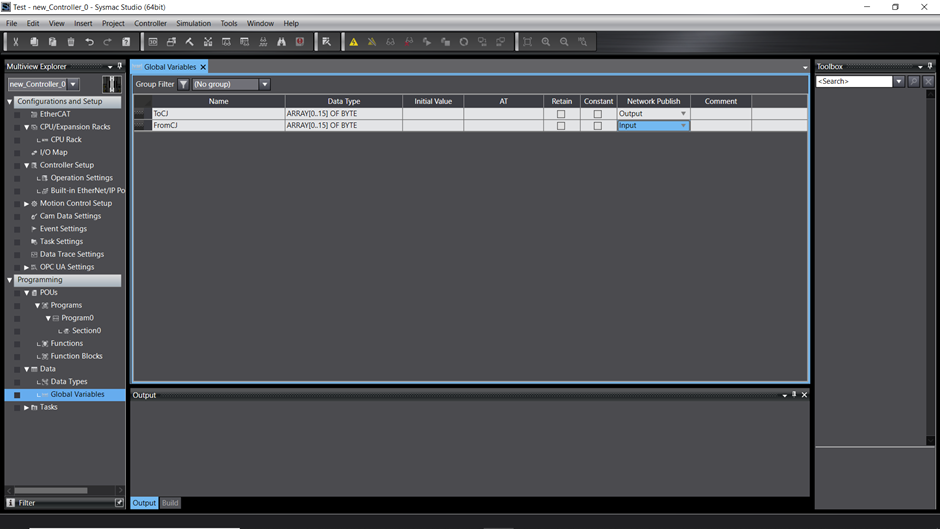
6. For the NJ PLC, create the tag sets using variable names instead of addressing as used for the CJ. Double click on the NJ101 to configure the tag sets. 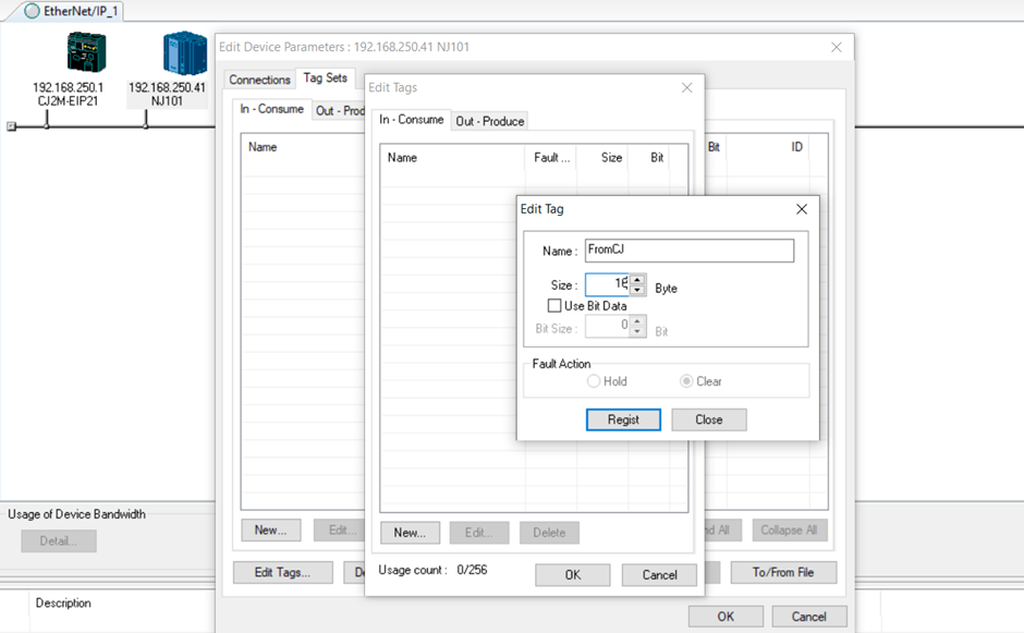
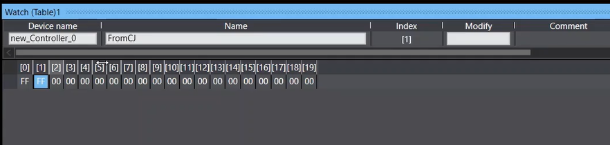
Notice that here, the tag name “FromCJ” is used. A direct addressing as used in the CJ can still be used (not shown in this example). Note that the tag size has to be the same for each of the device communicating. Ie: 16 bytes of data is transferred from the CJ to the NJ. The output tag for the CJ is 16 bytes and the input tag for the NJ is also 16 bytes.
7. Repeat the same process for the output tag for the NJ. 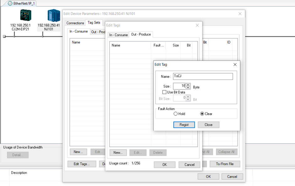
8. After creating the tag sets, create the connection between the device by dragging the device on top of each other. By dragging the CJ PLC onto the NJ PLC, it creates a slave -> master relationship. 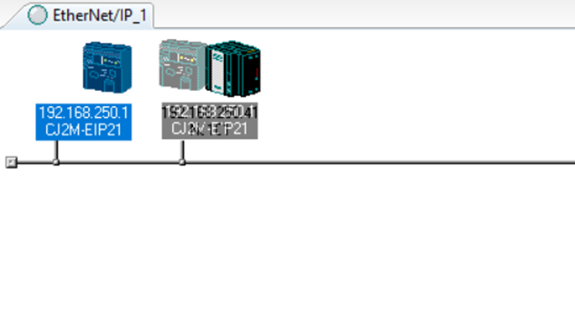
9. The following screen will show. Click on the highlighted box to link the tag sets together. Click register when the tags are selected, then click on “Close”.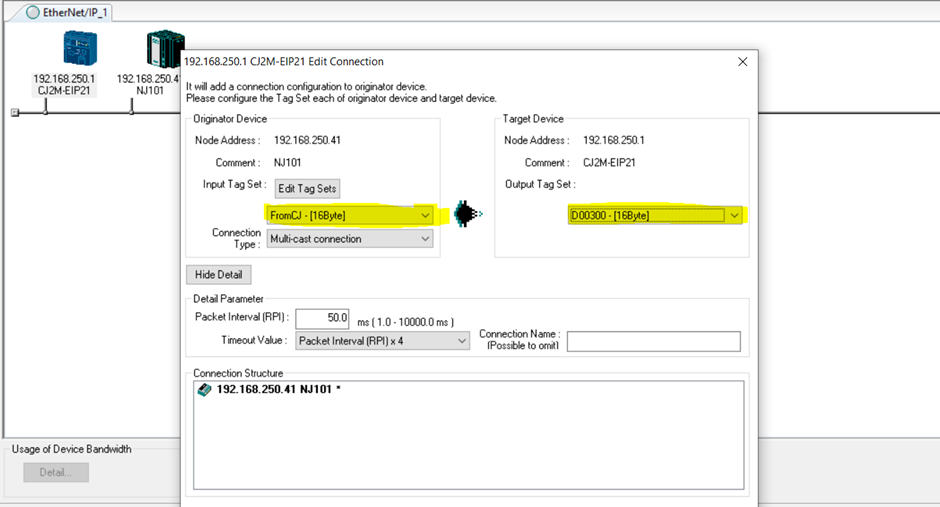
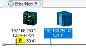
10. Once a connection is established, the arrow will show up under the corresponding device.
11. Do the same for the NJ -> CJ. 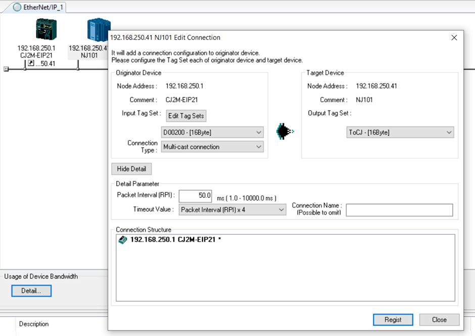
12. Once both the connections are configured, right-click and select “Download”. When downloading the tag sets to the PLC, the PLC changes into “Program Mode” momentarily unless option to keep in Run Mode is chosen.
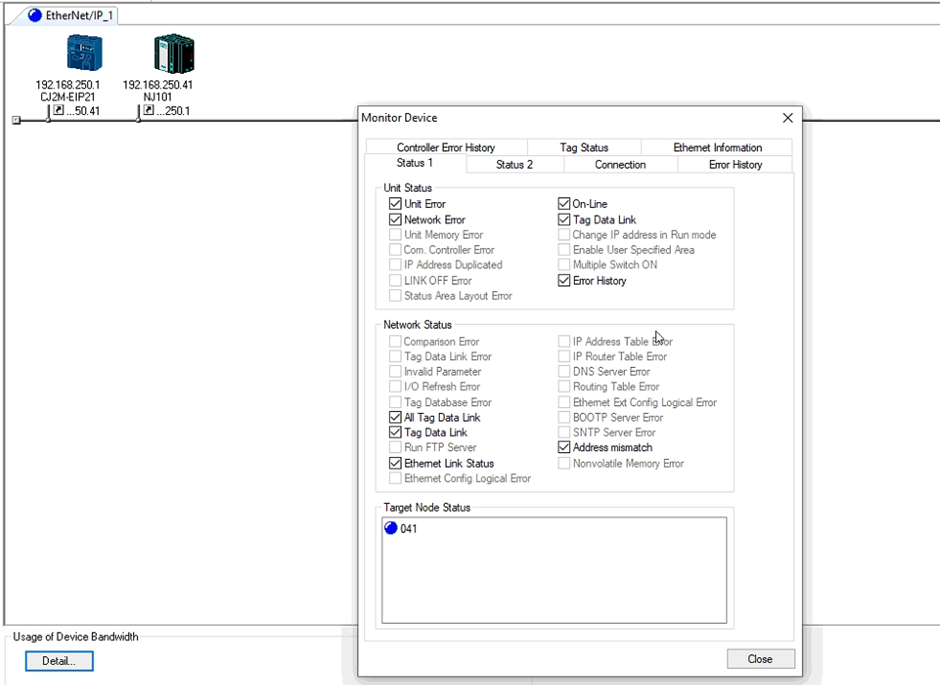
13. To check for the validity of the connection, right click on the devices and select “Monitor”.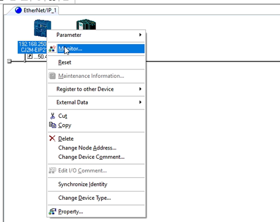
14. The target node represents the devices that the selected device is communicating with. When the target node is showing red, it shows that the connection is not established. 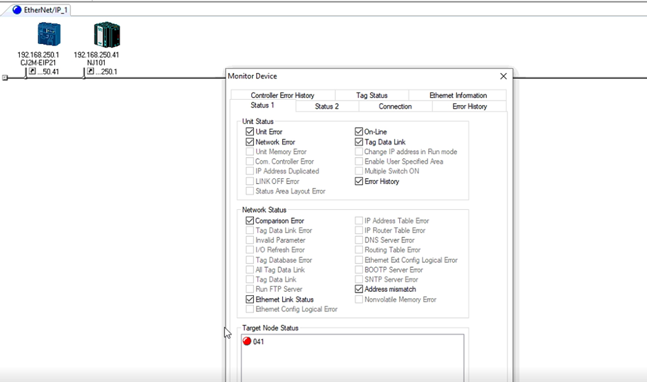
The connection is not established in this case is because the tag sets are not created in the NJ PLC. Network configurator creates the connection in between tag sets but not the variables to store them in. This is only required for the NJ since the tag sets are named variables and the tag sets for the CJ are directly addressed as they are preallocated.
Note: If instead of naming the tag sets "ToCJ" and "FromCJ", but using address as tag sets, the NJ101 would not show a red LED but a blue LED. This would be because the destination of the tag sets were set to the address but not variables.
16. Once the variables have been setup, go back into Network Configurator and monitor the connection status again. The status of the connection will show up blue if the connection is established.
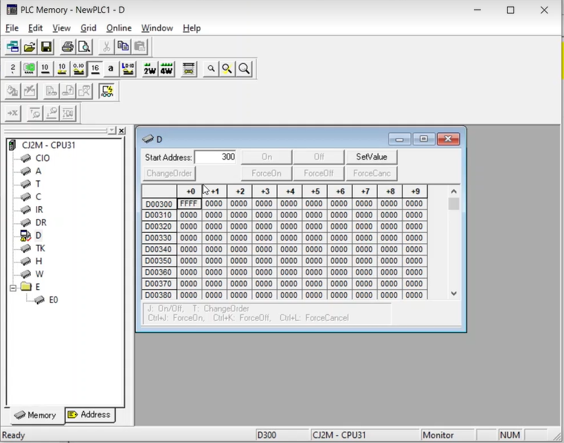
17. To further verify that the tag sets are transferring data, if any number was input into the D300 tag from CX Programmer, it would reflect in "From CJ" tag on the NJ101. This can be checked by going into Sysmac Studio and monitoring the tag.
Step 5 - Adding Third-Party Devices
When adding third party devices, add the corresponding EDS file for each of the devices. Omron devices will already have their EDS file installed on Network Configurator. Third party EDS files will be provided by the product's supplier.
1. To install EDS files, go into Network Configurator -> EDS File -> Install. Locate the EDS file on the PC and install. The corresponding device will show up on the left. Doing an upload will also add the device onto Network Configurator. 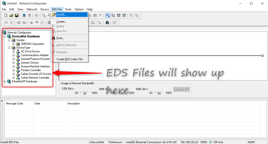
2. Repeat from step 3 to setup the third party device.
Reference
1) Variable types and size: https://www.myomron.com/index.php?action=kb&article=1628
2) NJ/NX series CPU Unit Built-in EtherNet/IP Port User’s Manual: https://www.edata.omron.com.au/eData/NJ/W506-E1-24.pdf
3) CJ2H/CJ2M CPU__-EIP EtherNet/IP Units Operation Manual: https://www.edata.omron.com.au/eData/Networks/EIP/W465-E1-09.pdf