Overview
This document provides examples and explanations of input and output wiring of a G9SE safety relay unit, including the G9SE-201, G9SE-401, G9SE-221-T05 and G9SE-221-T30.
Power Supply Input (A1, A2)
Connect the power supply's positive terminal to the G9SE's A1 terminal.
Connect the power supply's negative terminal to the G9SE's A2 terminal.
Please ensure that you use 24 VDC.
DeleteSafety Inputs (T11, T12, T21, T22)
For the G9SE safety relay to output ON signals from its safety outputs, both safety inputs (T12 and T22) must receive HIGH state signals.
To achieve this, the safety inputs can be configured as either 1-channel safety inputs, or 2-channel safety inputs.
1-Channel Safety Input
Connect a 24VDC supply to the G9SE's T12 and T22 terminals, with the appropriate safety switches or devices installed between the supply and the G9SE, such as in the below image.
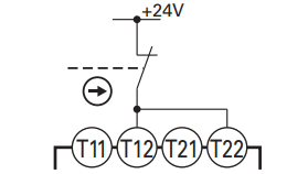
This will result in a HIGH-state signal to terminals T12 and T22, unless the switch is activated, in which case the signal will become LOW-state, causing the G9SE safety relay to switch OFF its outputs.
Note that terminals T11 and T21 are not connected in this case, and the switch in use is normally closed (NC).
Delete2-Channel Safety Input with a 2-Channel Sensor
Many safety sensors, such as light curtains, use 2-channel safety outputs to provide a greater degree of protection. Refer to the datasheet or manual of the safety sensor to determine if this is the correct connection type in the specific application.
Connect the safety sensor's outputs to the G9SE's T12 and T22 terminals, as shown in the below image.
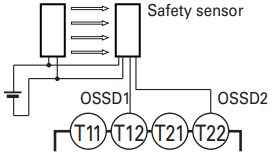
This will result in terminals T12 and T22 receiving HIGH or LOW-state signals depending on the operation of the safety sensor, causing the G9SE safety relay to switch its outputs ON or OFF accordingly.
Note that terminals T11 and T21 are not connected in this case.
Delete2-Channel Safety Input with a 2-Channel Switch
Safety switches typically feature dual switching, or 2-channel switching, to provide a greater degree or protection. Refer to the datasheet of the switch to determine if this is the correct connection type in the specific application.
Connect the first channel of the safety switch in a circuit loop between the G9SE's T11 and T12 terminals. Connect the second channel of the safety switch in a circuit loop between the G9SE's T21 and T22 terminals. These connections are shown in the below image.
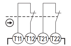
This will result in terminals T12 and T22 receiving HIGH-state signals from terminals T11 and T21, unless the switch is activated, in which case the signals will become LOW-state, causing the G9SE to switch OFF its outputs.
Note that the safety switch used is normally closed (NC).
DeleteReset/Feedback Loop (T31, T32, T33)
For the G9SE safety relay to output ON signals from its safety outputs, a reset or feedback loop must be connected.
The G9SE can be configured with either an automatic or manual reset.
Automatic Reset
Connect a 24VDC supply to the G9SE's T32 terminal.
Connect the G9SE's T31 terminal to the T33 terminal. A feedback circuit may be installed on this connection, to allow for greater control over the reset behaviour, as seen in the below image. Any feedback loop should be designed to be normally closed (NC) in the case of normal operation.
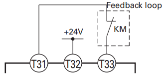
This will result in the G9SE's safety outputs being switched ON and OFF depending on the state of the safety inputs.
Note that the safety system should be designed taking into account that if the automatic reset configuration is used, the safety outputs will turn ON when both safety inputs receive HIGH-state signals.
DeleteManual Reset
Connect a 24VDC supply to the G9SE's T33 terminal.
Connect the G9SE's T31 terminal to a normally open reset switch, then to the T32 terminal. A feedback circuit may be installed on this connection, to allow for greater control over the reset behaviour, as seen in the below image. Any feedback loop should be designed to be normally closed (NC) in the case of normal operation.
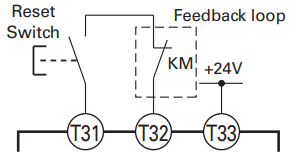
This will result in the G9SE's safety outputs being in the OFF state until the following procedure occurs:
- Both of the G9SE's safety inputs are supplied with a HIGH-state signal.
- The G9SE's T32 terminal is supplied with a HIGH-state signal, by closing the reset switch.
- The G9SE's T32 terminal is supplied with a LOW-state signal, by opening the reset switch.
Note that the G9SE's safety inputs must remain supplied with a HIGH-state signal throughout the above procedure.
DeleteSafety Outputs (13-14, 23-24, 33-34, 43-44)
The G9SE's safety outputs switch ON and OFF depending on the state of the safety and reset inputs.
Connect the load and load power supply in series with a safety output pair (terminals 13-14, 23-24, 33-34 or 43-44) on the G9SE, as shown in the below image.
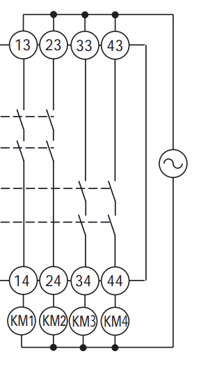
Note that different loads and load power supplies may be on isolated circuits, despite the above image showing four loads (KM1, KM2, KM3 and KM4) on the same power supply.
Depending on the model of the G9SE safety relay, different safety output terminals may be present.
The G9SE-201 possesses safety output terminals 13-14 and 23-24.
The G9SE-401 possesses safety output terminals 13-14, 23-24, 33-34 and 43-44.
The G9SE-221-T05 and G9SE-221-T30 both possess safety output terminals 13-14, 23-24, and off-delayed safety output terminals that will be discussed in a different section of this document.
The safety outputs detailed in this section are instantaneous safety outputs, meaning that once the conditions are reached for the G9SE to switch the safety outputs off, it does so without delay.
DeleteOff-Delayed Safety Output (37-38, 47-48)
The G9SE-221-T05 and G9SE-221-T30 both feature two off-delayed safety outputs (terminals 37-38 and 47-48). These safety outputs function in a similar manner to the other safety outputs on the G9SE, with the exception that after the conditions are reached for the G9SE to switch the safety outputs off, it does so after the delay period set using the off-delay preset switches, which can be up to five seconds for the T05 model, or up to thirty seconds for the T30 model.
Connect the load and load power supply in series with an off-delayed safety output pair (terminals 37-38 or 47-48) on the G9SE, as shown in the below image.
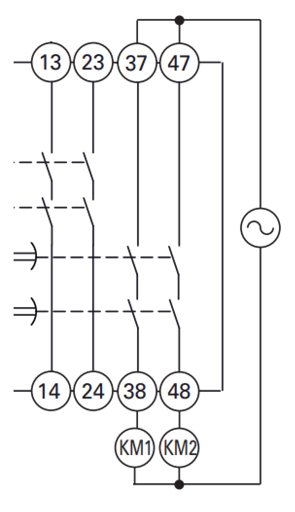
Note that the instantaneous outputs on the G9SE will function as normal, without the delay. Off-delay Safety Outputs may be used as instantaneous safety outputs, if the off-delay is set to zero seconds.
Regarding the off-delay preset switches, note that there are two off-delay preset switches, one on the front and one on the rear. These must be set to the same value. The correct setting position of an off-delay preset switch is shown in the below image. Note that the cutting edge of the rotary switch must face the desired setting value.
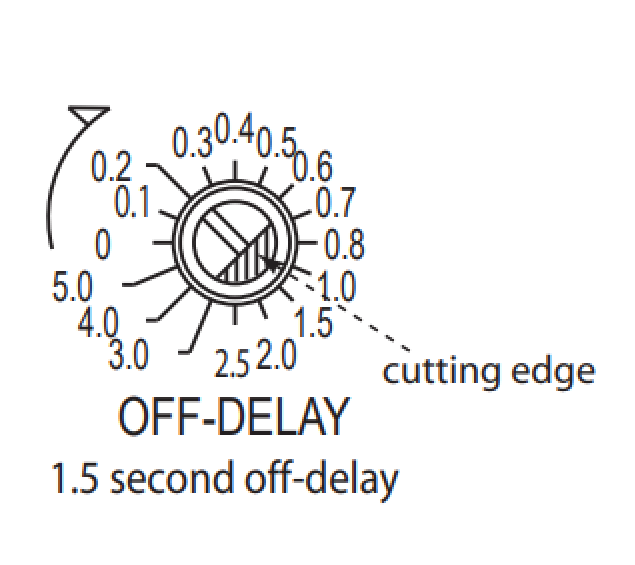
Only change the position of the off-delay preset switches when the G9SE is disconnected from the power supply.
DeleteAuxiliary Output (X1)
The G9SE's X1 terminal is an auxiliary output, which outputs a signal of the same logic as the safety outputs.
Connect the X1 terminal to the appropriate digital input on a PLC or other monitoring device.
Note that the auxiliary output is not a safety output, and should not be used as a safety output.
DeleteOnce the wiring of the G9SE is complete, it should be operational. If it is not operational, the indicator lights will assist in troubleshooting the issue. Please consult the G9SE fault detection guide, located here.