Introduction
The purpose of this step-by-step guide is to provide a walkthrough for establishing a connection between an NA series Human Machine Interface (HMI) and a CJ series Programmable Logic Controller (PLC).
Pre-Requisites
Basic knowledge of Sysmac Studio and CX-Programmer software.
Understanding of IP addresses and basic network structure.
Procedure
Supported PLCs
Ensure that your CJ series PLC is supported by the NA Series HMI. This can be done by checking if your CJ-series PLC features a Built-In EtherNet/IP port.
If your CJ series PLC does not feature a Built-In EtherNet/IP port, you will require an expansion communications unit, being either a CJ1W-ETN21 or a CJ1W-EIP21. Please consult the below table to ensure that the appropriate unit is selected.
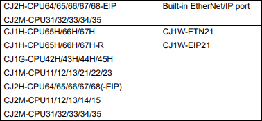
Note that there are two different communications drivers that can be used to connect an NA HMI to a CJ PLC, namely CIP Ethernet and FINS Ethernet. All of the CJ series PLCs in the above table are able to communicate via FINS ethernet, so long as they have either the Built-In EtherNet/IP port, or one of the two communication units installed.
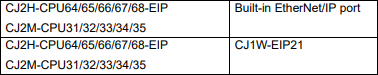
In order to use the CIP Ethernet communications method, the PLCs in the below table must be used. Note that this connection can be through either the Built-In EtherNet/IP port, or an installed CJ1W-EIP21.
Physical Setup
The NA series HMI can be connected to the CJ series PLC in two different physical configurations.
The first configuration is a direct connection between the NA series HMI and the CJ PLC, as shown in the below image.
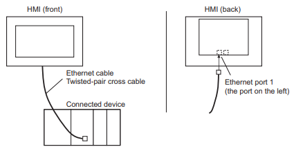
For this configuration, ensure that a twisted-pair cross cable ethernet cable is used, and that it is connected to ethernet port 1 on the NA series HMI.
The second configuration is a connection using an ethernet switch, which allows for multiple HMIs and other connected devices, as shown in the below image.
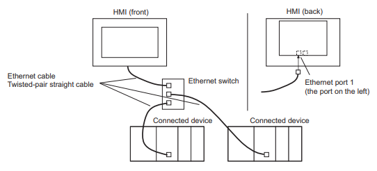
For this configuration, ensure that a twisted-pair straight cable ethernet cable is used for all connections between the ethernet switch and connected devices, including the NA series HMI, and that the cable is connected to ethernet port 1 on the NA series HMI.
Connecting using FINS Ethernet,
Before continuing with the setup, if you wish to connect your NA series HMI to your CJ series PLC using the CIP Ethernet communication protocol, please proceed directly to the 'Connecting using CIP Ethernet' section, below this one.
Note that the CJ series PLC is programmed and configured using CX-Programmer, while the NA series HMI is programmed and configured using Sysmac Studio.
Step 1 - CJ series PLC Front Panel Switches
Always turn off the device before changing the rotary switches.
If using the Build-In EtherNet/IP port on the PLC, set the unit number and FINS node address with the front panel rotary switches on the PLC. If using an expansion communications unit, such as the CJ1W-ETN21 or CJ1W-EIP21, set the unit number and FINS node address with the front panel rotary switches on the specific communications unit.
To set the unit number, use a small screwdriver to turn the rotary switch marked 'UNIT No.'. The switch can be set from 0 to F, and it is important that each unit on the network have a unique unit number.
To set the FINS node number, use a small screwdriver to turn the two rotary switches marked 'NODE No.'. Note that the two switches are also marked with a 'x160' and a 'x161', where the former sets the units column of the two digit number, and the latter sets the tens column. While the switches can be set from 0 to F, the allowable range for the FINS node number is between 01 and 7E, which corresponds to a decimal value between 1 and 126.
Note that the FINS node number must be the same as the last octet, or number, of the IP address of the PLC or communications unit.
Turn on the PLC.
Step 2 - CJ series PLC Settings
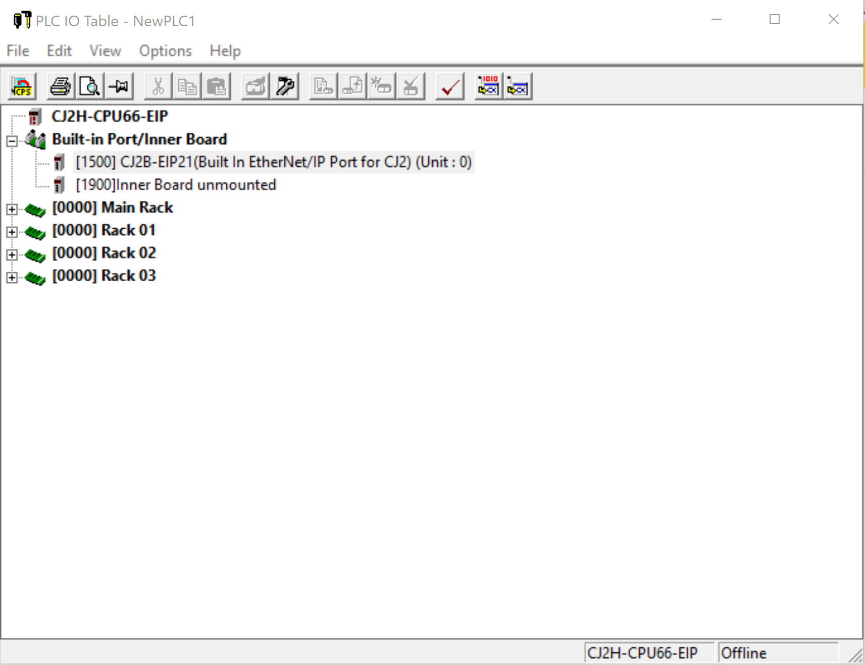
Open CX-Programmer, create a new program (ctrl+n), connect to the PLC (ctrl+w) and transfer from the PLC (ctrl+shift+t). once the program is transferred from the PLC to CX-Programmer, double-click on the 'IO Table and Unit Setup' entry on the tree diagram to the left of the window. This will open the PLC IO Table, as seen below.

In the above image, a CJ series PLC with a Built-In Ethernet/IP port is used. If an expansion communications unit is used, it will appear under Main Rack or Racks 1 through 3, depending on the exact location of its installation. If the communications unit does not appear, use the buttons at the top of the window to 'Transfer IO Table from PLC'. If this does not cause the communications unit to appear, use the 'Create Registered IO Table' button at the top of the window. If this does not cause the communications unit to appear, manually add the communications unit by right-clicking on the appropriate empty slot and selecting 'Add Unit', then select the appropriate device.
Right-click on either the Built-In EtherNet/IP port or the communications unit to be used, and select 'Unit Setup'. This will open the window for editing the parameters of the PLC or communications unit, as seen below.
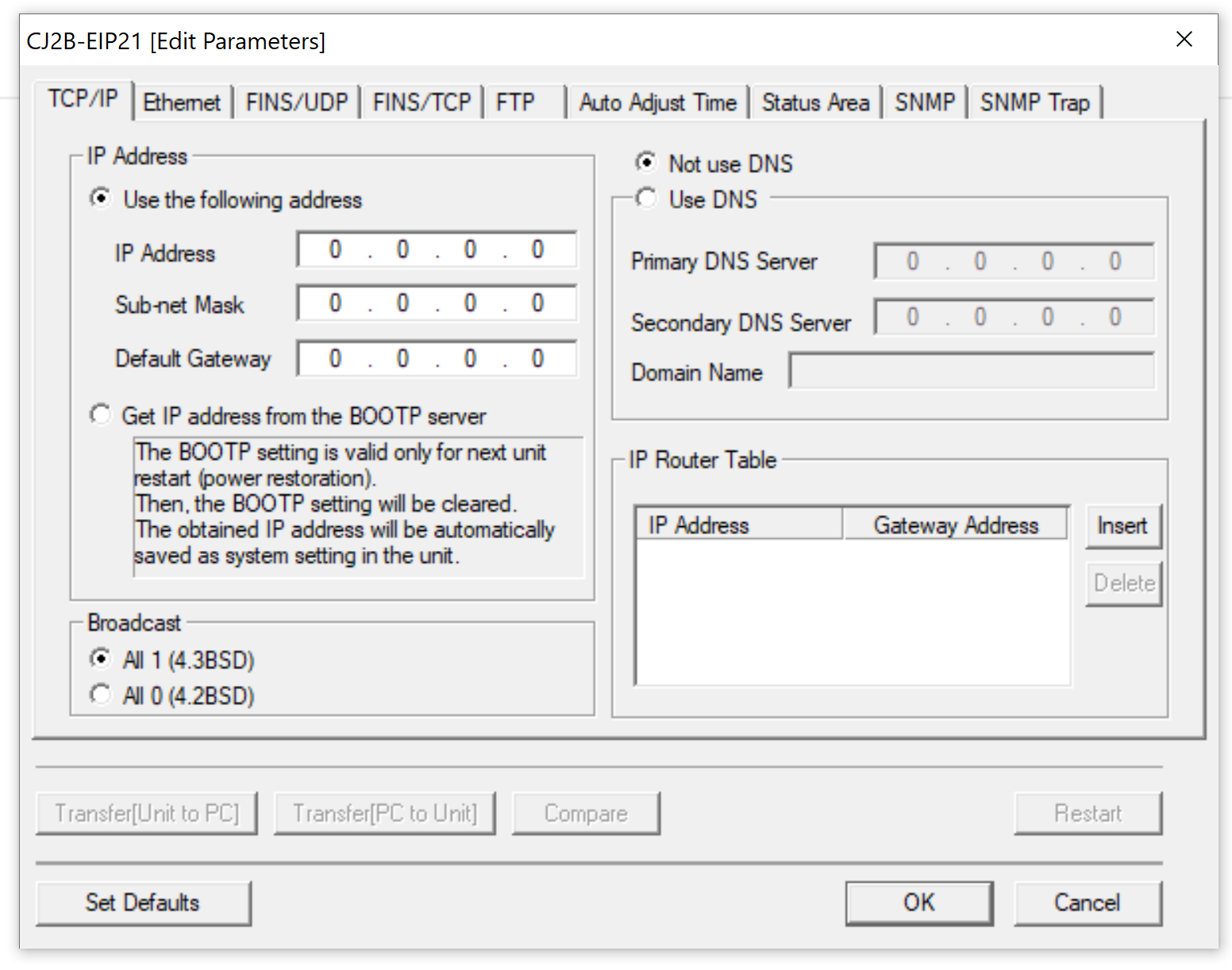
In this window, set the following items.
From the TCP/IP tab,
- IP address (Note that the last number of the IP address must match the previously set FINS node number).
- Subnet Mask
- Default Gateway
From the Ethernet tab,
- LINK Setting (Using the default value of 'Auto' is recommended).
From the FINS/UDP tab,
- FINS/UDP Port No. (Use the default value of 9600).
- IP Address Conversion (Use either of the Automatic methods).
- Destination IP Address (set to 'Destination IP is Not changed dynamically).
Once these settings are made, click 'OK' to close the window, then use the buttons at the top of the PLC IO Table to 'Transfer IO Table to PLC'.
Right-click on either the Built-In EtherNet/IP port or the communications unit to be used, and select 'Start Special Application', then 'Start with Settings Inherited'. The program may ask you to select CX-Integrator or Network Configurator. Select CX-Integrator. This will open CX-Integrator in a new window.
Step 3 - CX-Integrator
In the CX-Integrator window, select 'Work Online' from the buttons at the top of the screen, then select 'Tools' from the menus at the top of the window, followed by selecting 'Start Routing Table'. This will open the PLC Routing Table window, as seen below. A routing table must be created as the NA HMI exists on Network #1 by default, while the CJ PLC exists on Network #0. The routing table allows the PLC and HMI to exist and communicate on the same network.
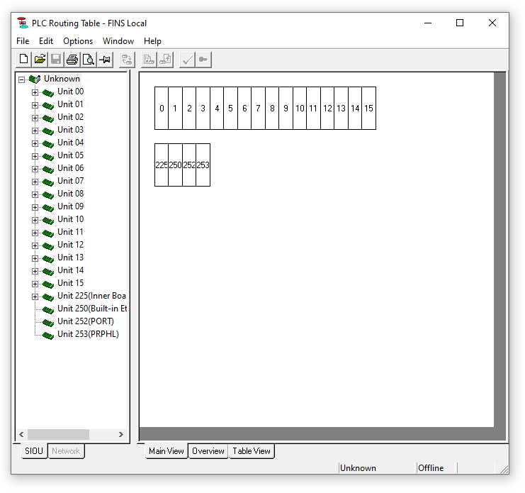 If you are using expansion communications units, you should see them on the left side of the window. If you do not see them, use the buttons at the top of the screen to 'Transfer from the PLC'. Note that the unit numbers correspond to the unit numbers originally set on the front rotary switches.
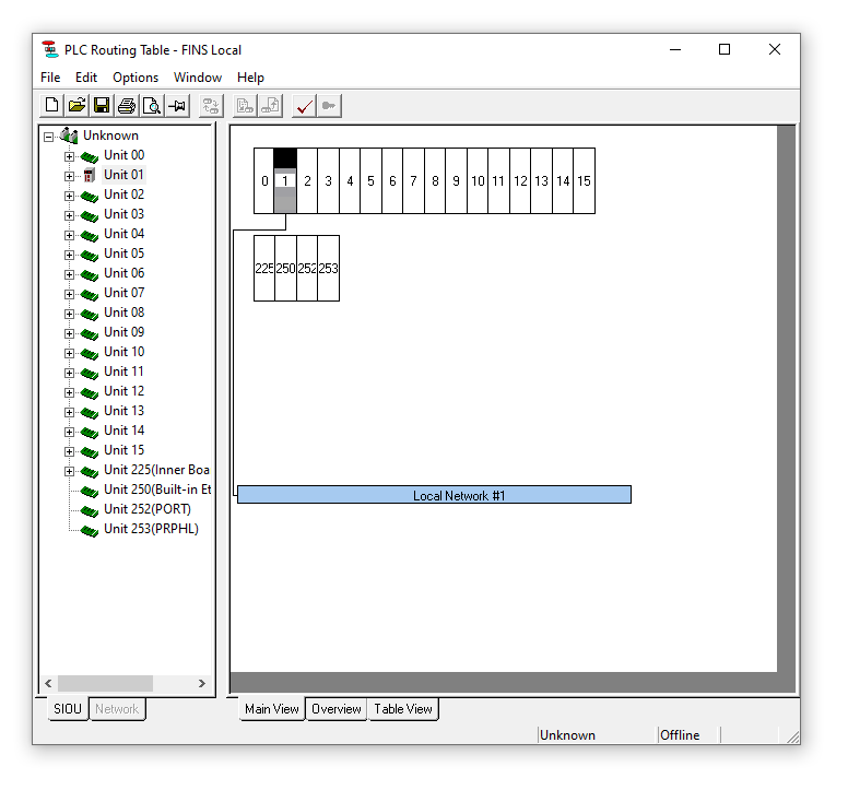
Right-click on the unit that will be used for connecting to the NA series HMI. Note that if the Built-In EtherNet port is used, the unit number is Unit 250 (Built-in Ethernet Port). Select 'Insert CPU SIOU', and ensure that the Local Network Number in the pop-up window is set to '1'. Click OK, then use the buttons at the top of the window to 'Transfer to the PLC'.
An example of a complete routing table is below. Note that the unit number used in the example is Unit 01, which may be different as discussed above.
You can now disconnect CX-Integrator from the CJ-series PLC, and close CX-Integrator.
Step 4 - CX-Programmer Global Variables
In order to have the NA series HMI access variables on the CJ series PLC, those variables must be created and registered as global variables. Ensure that all of the required variables are created for use in your PLC and HMI programs. Use the buttons at the top of CX-Programmer to transfer the program to the PLC.
Keep CX-Programmer open.
Step 5 - NA series HMI Settings
Open Sysmac Studio. Create and new project or open an existing project as appropriate. Ensure that the HMI in the project is the same as your NA series HMI.
Use the buttons at the top of the window to go Online with the NA series HMI, and then Synchronise and transfer from the HMI to your PC.
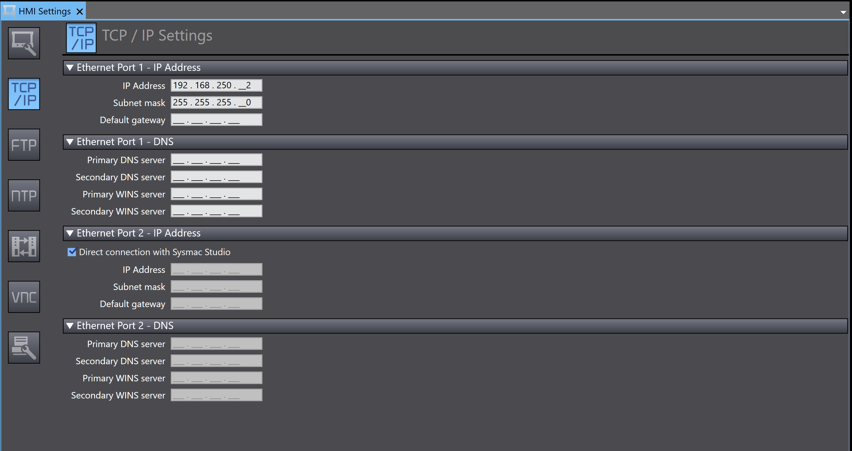
In the Multiview Explorer on the left of the window, double-click 'HMI Settings', which is located in the 'Configurations and Setup' section. In the tab that opened, select the 'TCP/IP Settings' button on the left side. This will open the tab shown below.

In this tab, set the IP address, subnet mask and default gateway for Ethernet port 1.
Once these settings are made, click on the 'FINS Settings' button on the left side. This will open the tab shown below.
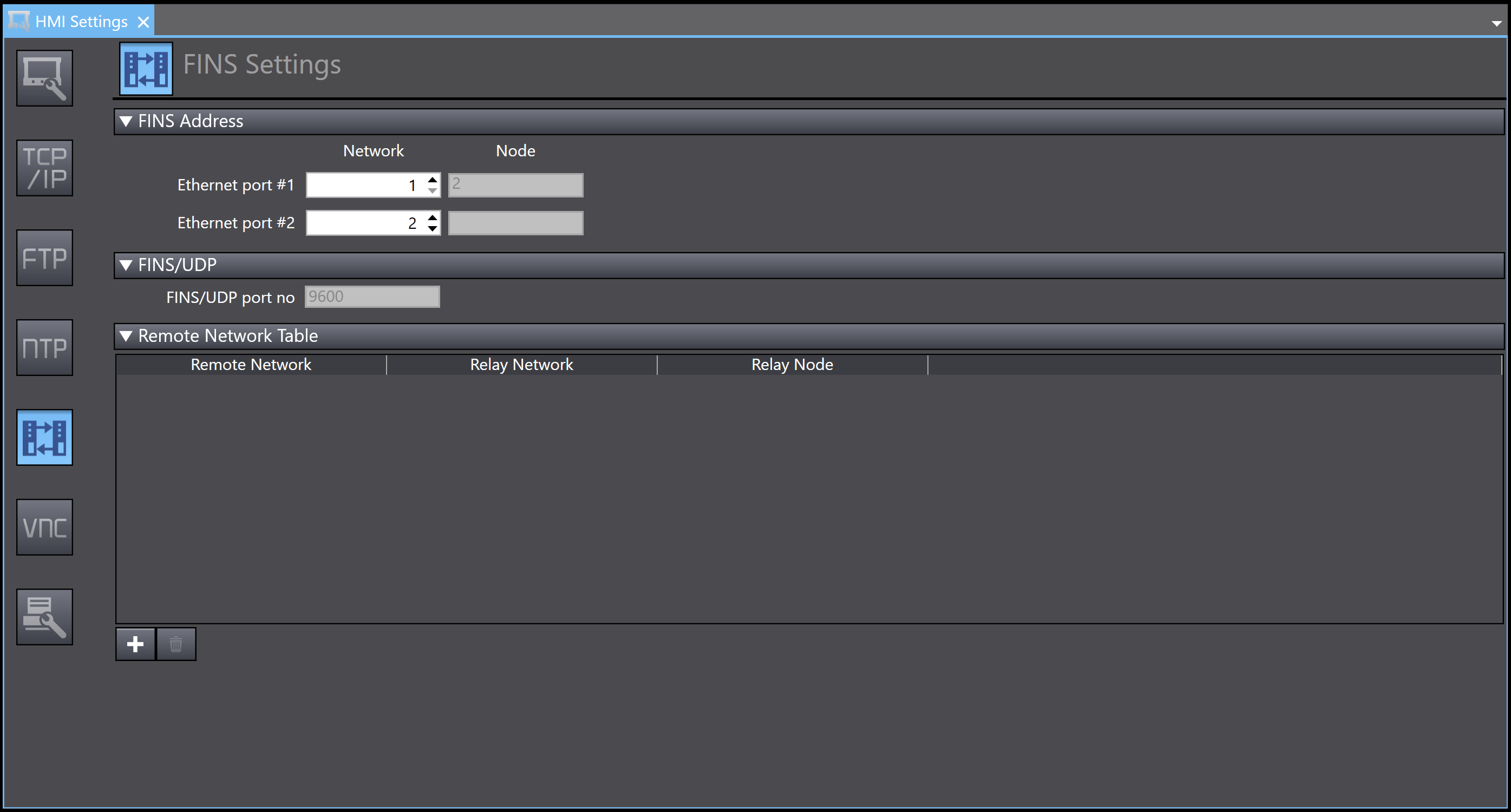
Ensure that Ethernet port #1 is set to Network 1. The HMI Settings tab can be closed now.
Step 6 - Registering the CJ series PLC in Sysmac Studio
In the Multiview Explorer on the left side of Sysmac Studio, right-click 'Device References', located under 'Configuration and Setup', and select 'Add' then 'external device'. This will add a generic external device with a name similar to 'ExternalDevice0', underneath 'Device References'.
Double-click the newly added external device. This will open the tab shown below.
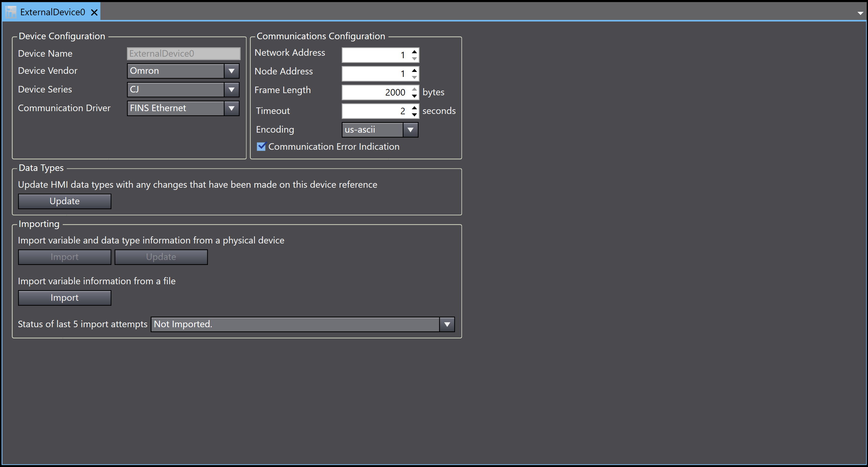
In this tab, ensure that the following settings are made.
- Device Vendor: Omron
- Device Series: CJ
- Communications Driver: FINS Ethernet
- Network Address: 1
- Node Address: This is the node number of the PLC.
- Frame Length: 2000 bytes as default. Change if necessary.
- Timeout: 2 seconds as default. Change if necessary.
- Encoding: us-ascii as default. Change if necessary.
Step 7 - Registering Device Variables
Return to CX-Programmer, and locate the global variables list.
Select the required global variables, then right-click and select 'copy'.
Return to Sysmac Studio, and in the Multiview Explorer, locate the 'Variables' entry, under the external device added in the previous step. Double-click this entry to bring up the variable table. Right-click on this table and select 'Paste'.
Alternatively, a CXT file can be obtained from CX-Programmer and imported into Sysmac Studio, using the 'Import' button under 'Import variable information from a file' in the previous image's tab.
Once the variable information is registered, you can go online with the HMI, synchronise, and then transfer the program to the HMI.
Your NA series HMI and CJ series PLC are now connected and able to communicate using the registered global variables.
Connecting using CIP Ethernet
Note that the CJ series PLC is programmed and configured using CX-Programmer, while the NA series HMI is programmed and configured using Sysmac Studio.
Step 1 - CJ series PLC Front Panel Switches
Always turn off the device before changing the rotary switches.
If using the Build-In EtherNet/IP port on the PLC, set the unit number with the front panel rotary switches on the PLC. If using an expansion communications unit, such as the CJ1W-EIP21, set the unit number with the front panel rotary switches on the specific communications unit.
To set the unit number, use a small screwdriver to turn the rotary switch marked 'UNIT No.'. The switch can be set from 0 to F, and it is important that each unit on the network have a unique unit number.
Turn on the PLC.
Step 2 - CJ series PLC Settings
Open CX-Programmer, create a new program (ctrl+n), connect to the PLC (ctrl+w) and transfer from the PLC (ctrl+shift+t). once the program is transferred from the PLC to CX-Programmer, double-click on the 'IO Table and Unit Setup' entry on the tree diagram to the left of the window. This will open the PLC IO Table, as seen below.
In the above image, a CJ series PLC with a Built-In Ethernet/IP port is used. If an expansion communications unit is used, it will appear under Main Rack or Racks 1 through 3, depending on the exact location of its installation. If the communications unit does not appear, use the buttons at the top of the window to 'Transfer IO Table from PLC'. If this does not cause the communications unit to appear, use the 'Create Registered IO Table' button at the top of the window. If this does not cause the communications unit to appear, manually add the communications unit by right-clicking on the appropriate empty slot and selecting 'Add Unit', then select the appropriate device.
Right-click on either the Built-In EtherNet/IP port or the communications unit to be used, and select 'Unit Setup'. This will open the window for editing the parameters of the PLC or communications unit, as seen below.

In this window, set the following items.
From the TCP/IP tab,
- IP address
- Subnet Mask
- Default Gateway
From the Ethernet tab,
- LINK Setting (Using the default value of 'Auto' is recommended).
Once these settings are made, click 'OK' to close the window, then use the buttons at the top of the PLC IO Table to 'Transfer IO Table to PLC'.
Step 3 - CX-Programmer Global Variables
In order to have the NA series HMI access variables on the CJ series PLC, those variables must be created and registered as global variables. When the variables are registered, ensure that 'Network Variable' and either 'Input' or 'Output', depending on the use of the variable in your program.
Ensure that all of the required variables are created for use in your PLC and HMI programs. Use the buttons at the top of CX-Programmer to transfer the program to the PLC.
Keep CX-Programmer open.
Step 4 - NA series HMI Settings
Open Sysmac Studio. Create and new project or open an existing project as appropriate. Ensure that the HMI in the project is the same as your NA series HMI.
Use the buttons at the top of the window to go Online with the NA series HMI, and then Synchronise and transfer from the HMI to your PC.
In the Multiview Explorer on the left of the window, double-click 'HMI Settings', which is located in the 'Configurations and Setup' section. In the tab that opened, select the 'TCP/IP Settings' button on the left side. This will open the tab shown below.
In this tab, set the IP address, subnet mask and default gateway for Ethernet port 1.
The HMI Settings tab can be closed now.
Step 5 - Registering the CJ series PLC in Sysmac Studio
In the Multiview Explorer on the left side of Sysmac Studio, right-click 'Device References', located under 'Configuration and Setup', and select 'Add' then 'external device'. This will add a generic external device with a name similar to 'ExternalDevice0', underneath 'Device References'.
Double-click the newly added external device. This will open the tab shown below.
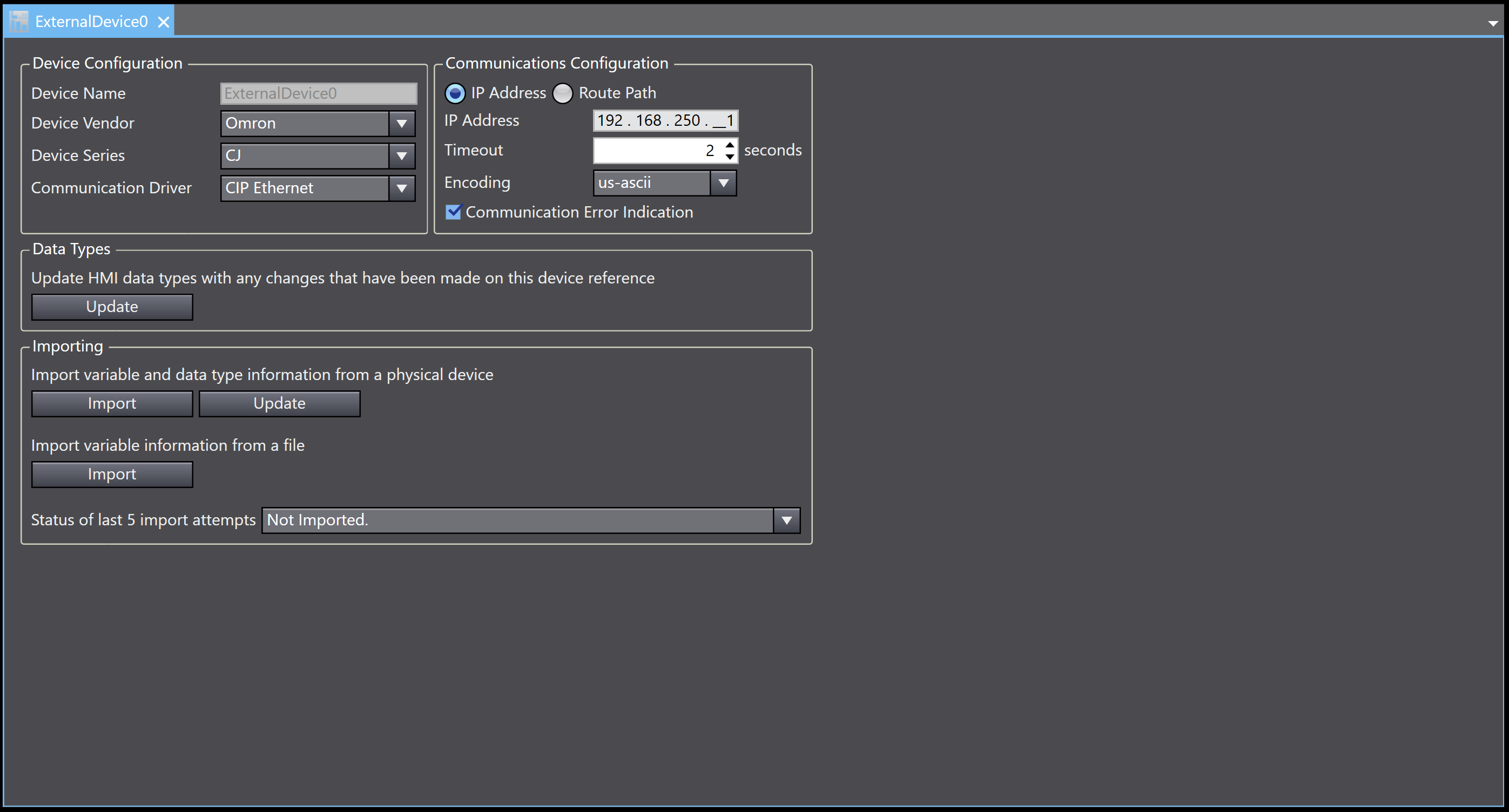
In this tab, ensure that the following settings are made.
- Device Vendor: Omron
- Device Series: CJ
- Communications Driver: CIP Ethernet
- Select 'IP Address', then enter the IP address of the PLC.
- Timeout: 2 seconds as default. Change if necessary.
- Encoding: us-ascii as default. Change if necessary.
Step 6 - Registering Device Variables
In the same external device settings tab, locate the 'Import' button underneath 'Import variable and data type information from a physical device'. Click this button to import the global variables from the CJ series PLC.
Alternatively, return to CX-Programmer, and locate the global variables list.
Select the required global variables, then right-click and select 'copy'.
Return to Sysmac Studio, and in the Multiview Explorer, locate the 'Variables' entry, under the external device added in the previous step. Double-click this entry to bring up the variable table. Right-click on this table and select 'Paste'.
Alternatively, a CXT file can be obtained from CX-Programmer and imported into Sysmac Studio, using the 'Import' button under 'Import variable information from a file' in the previous image's tab.
Once the variable information is registered, you can go online with the HMI, synchronise, and then transfer the program to the HMI.
Your NA series HMI and CJ series PLC are now connected and able to communicate using the registered global variables.