Introduction
This article is explains how a connection can be established with a CP1L (CP1W-01) using Host Link (RS232C) and two MX2 Inverters using Modbus RTU.
Content
- Connection Methods
- Wiring diagram
- HMI Attribute settings
- PLC Attribute and PLC settings (PLC0)
- PLC Attribute and PLC settings (PLC2)
- PLC Attribute and PLC settings (PLC3)
- Example program
1. Connection Methods
Host Link (RS232C)
NB with CP1L through COM1/RS232 (Host Link)
Modbus RTU (RS485)
NB with two MX2’s through COM2/RS485 (RS485)
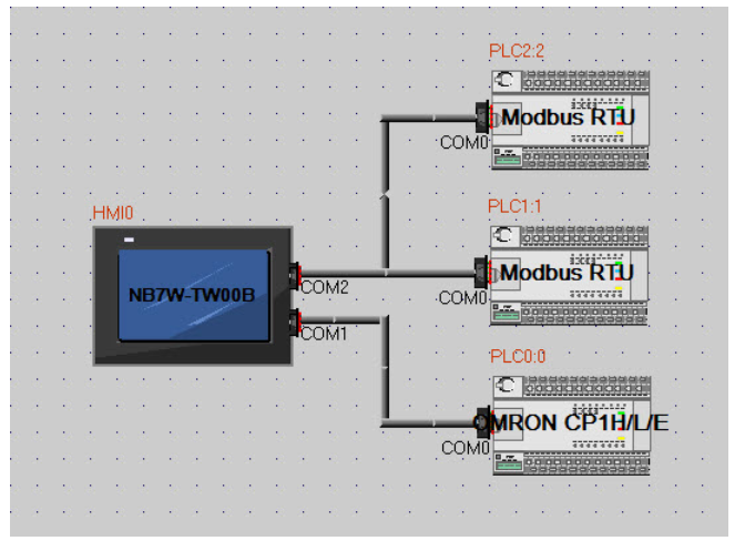
Start NB-designer, create a new program, drag and drop the NB, the CP1L and the two Modbus RTU’s on the “Project Structure Window”. Connect with the Serial connection line the CP1L’s to the COM1 port of the NB. Connect with the Serial connection line the Modbus RTU’s to the COM2 port of the NB.
2. Wiring diagram
COM1 Wiring diagram
NB pin 2 (SD) to CP1L (CP1W-CIF01) pin 3 (RD)
NB pin 3 (RD) to CP1L (CP1W-CIF01) pin 2 (SD)
NB pin 9 (SG) to CP1L (CP1W-CIF01) pin 9 (SG)
CP1W-CIF01 Bridge between pin 4 (RS) and pin 5 (CS)
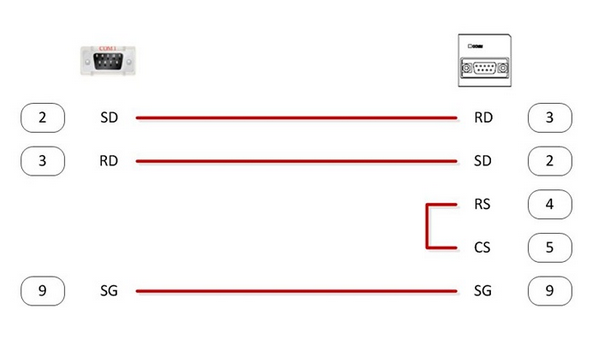
(Default cable: XW2Z-200T or XW2Z-500T)
Information
In order to avoid malfunctions caused by interference, shield the cables properly.
COM2 Wiring diagram
NB pin 6 (RDB+) to MX2 (RS+)
NB pin 8 (RDA-) to MX2 (RS-)
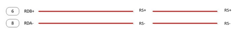
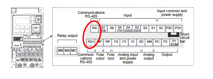
Set the Resistor switch at the last MX2 in the RS485 Network.
Information
In order to avoid malfunctions caused by interference, shield the cables properly.
3. HMI Attribute settings
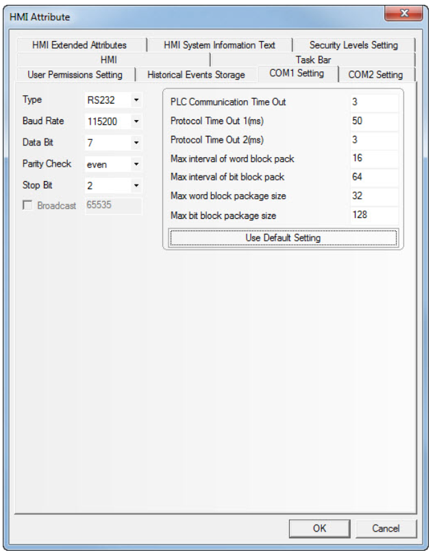
Double click on the NB in the “Project Structure Window” to open the HMI Attribute.
Select the ‘COM1 Settings’ tab and set the Host Link Communication settings to Type (RS232), Baud Rate (115200), Data Bit (7), Parity Check (Even) and Stop Bit to (2).
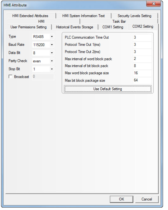
Select the ‘COM2 Settings’ tab and set the Modbus RTU Communication settings to Type (RS485), Baud Rate (115200), Data Bit (8), Parity Check (Even) and Stop Bit to (1).
4. PLC Attribute and PLC settings (PLC0)
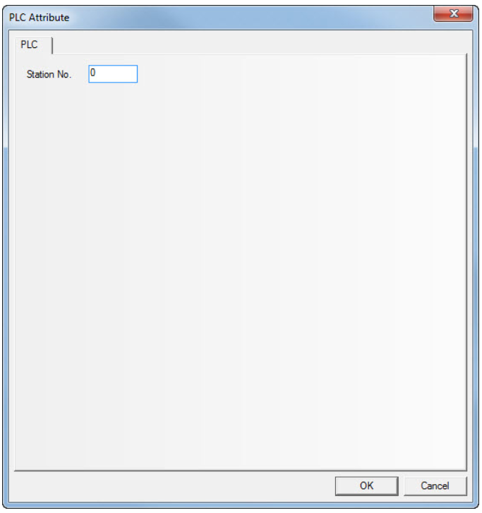
Double click on the CP1 in the “Project Structure Window” to open the PLC Attribute.
Set the Station No. to (0) in the PLC tab.
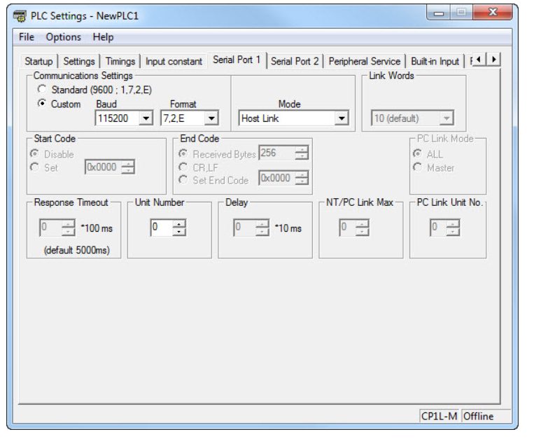
Start CX-Programmer, create a new program and select a CP1L. Open the Settings properties. Select the Serial Port 1 or Port 2 tab where CP1W-CIF01 is mounted.
Set the communication Settings to Custom, Baud (115200), Format (7,2,E), Mode (Host Link) and Unit Number to (0).
5. PLC Attribute and MX2 settings (PLC1)
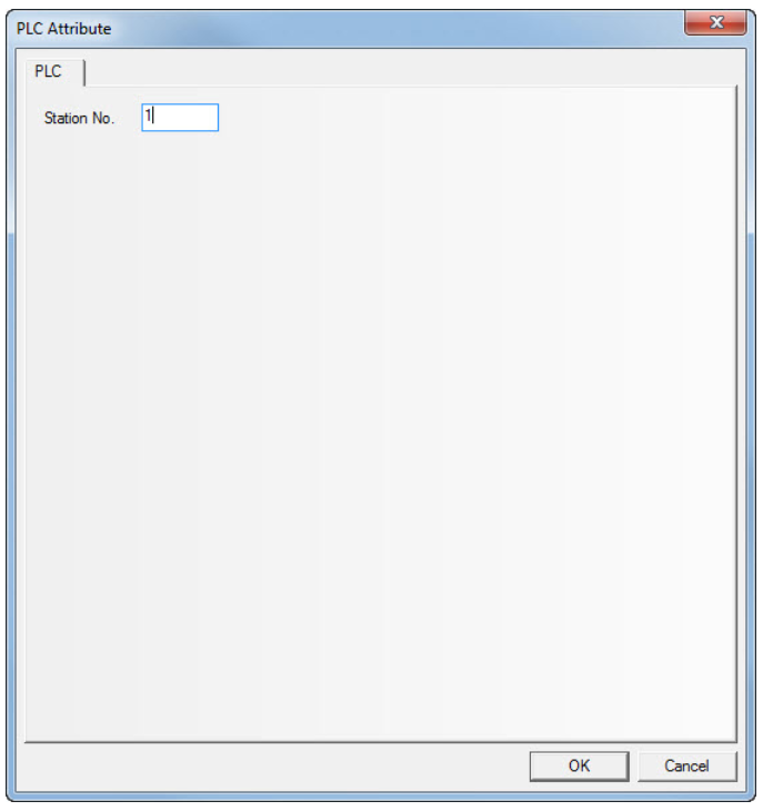
In NB-Designer, double click on the Modbus RTU (PLC1) in the “Project Structure Window” to open the PLC Attribute.
Set the Station No. to (1) in the PLC tab.
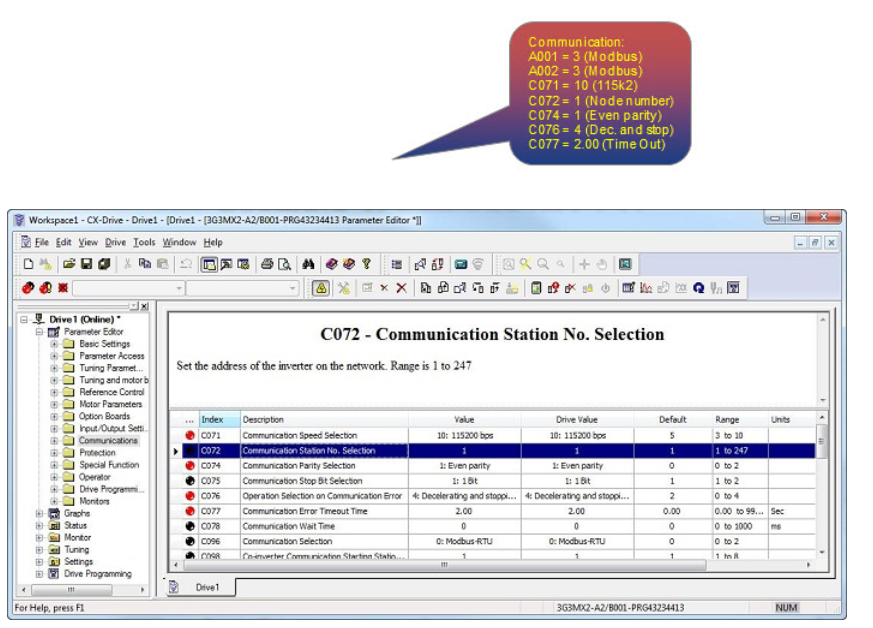
Start CX-Drive, create a new program and select a MX2. Initialize the MX2 and set the motor values. Go to the ‘Basic Settings’ and set parameter A001 and A002 both to 3 (Modbus). In the ‘Communication’ selection set the parameters C071 to 10 (115200), C072 to 1 (Station No), C074 to 1 (Even parity), C076 to 4 (Deceleration and stopping the motor) and C077 to 2.00 (Communication Error Timeout Time).
6. PLC Attribute and MX2 settings (PLC2)
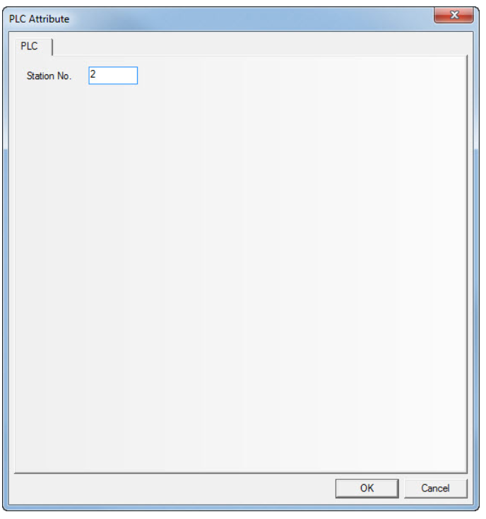
In NB-Designer, double click on the Modbus RTU (PLC2) in the “Project Structure Window” to open the PLC Attribute.
Set the Station No. to (2) in the PLC tab.
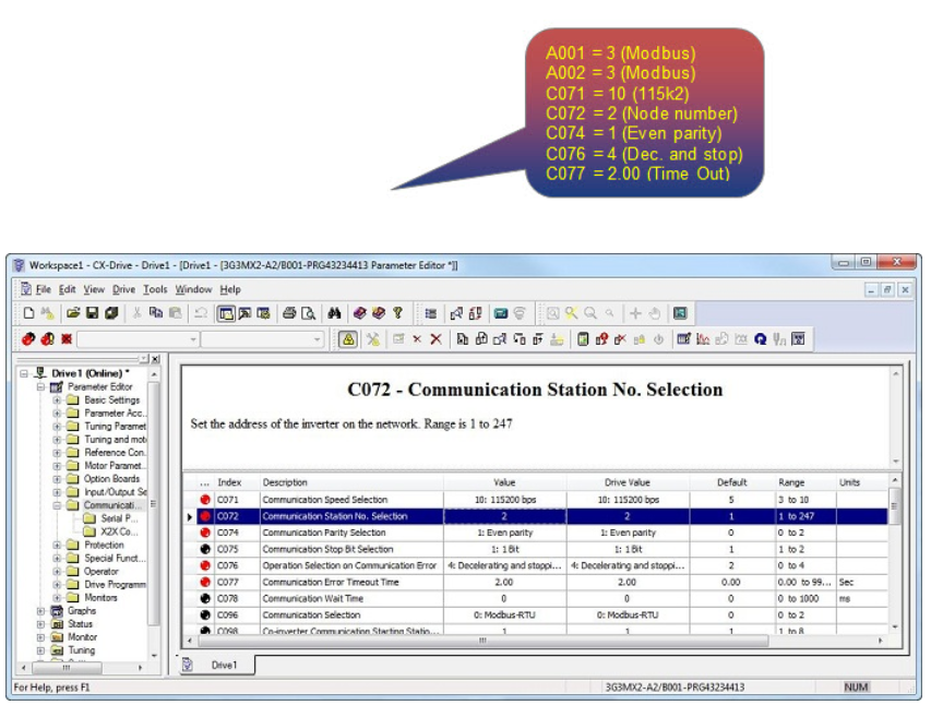
Start CX-Drive, create a second new program and select a MX2. Initialize the MX2 and set the motor values. Go to the ‘Basic Settings’ and set parameter A001 and A002 both to 3 (Modbus). In the ‘Communication’ selection set the parameters C071 to 10 (115200), C072 to 2 (Station No), C074 to 1 (Even parity), C076 to 4 (Deceleration and stopping the motor) and C077 to 2.00 (Communication Error Timeout Time).
 Save, compile and download the NB program, CX-Programmer and CX-Drive settings to the units and restart all.
7. Example program
Program versions: NB-Designer version 1.23 and CX-Programmer version 9.4
Attached file:
NB_With_CP1L_Through_COM1-RS232_Host_Link__And_MX2__2pcs__Through_COM2-RS485_Modbus_RTU_.zip
Example program for a NB7W-TW00B with a CP1L(PLC0) screen for Read/Write data to the CP1L through Host Link (RS232C). Two MX2 screens for send and receive data from the Inverters through Modbus RTU. And a NB Setup screen to Adjust settings like Date, Time, Buzzer, Screen Saver, Brightness adjust and Calibrate screen.
For the CP1L-M there is a CX-Programmer file with the Communication settings for Serial Port 1 and for the MX2’s there are CX-Drive file’s with the Communication settings (default motor parameters).
References:
CP1L Operation Manual (Cat. No. W462)
MX2 Users Manual (Cat. No. I570)
Programmable Terminals Host Connection Manual (Cat. No. V108)
Programmable Terminals NB-Designer Operation Manual (Cat. No. V106)
Programmable Terminals Setup Manual (Cat. No. V107)
Programmable Terminals Startup Guide Manual (Cat. No. V109)
NB-series Manuals (included in NB-designer)