Introduction
Setting up routing table for NJ to CJ1W-DRM21 for purpose of remote access/configuration of DeviceNet network via Ethernet connection.
Equipment Used and Settings:
- NJ301-1100 (default IP address 192.168.250.1, Default Subnet: 255.255.255.0)
- CJ1W-DRM21 with DRT2-ID16-1 /OD16-1 Devicenet Slaves
PC Settings:
- IP address = 192.168.250.200
- Subnet = 255.255.255.0
Further Reading
Please refer to these Precautions and Terms and Conditions which relate to the information and program samples provided before proceeding
CX-Integrator Further Reading
CX-Integrator
CX-Integrator is a Programming Device software package that enables reading the PLC's network and serial network configuration from a personal computer via an online connection. This enables easily performing many operations, such as monitoring the connection status of various networks, setting parameters, and diagnosing networks.
For the purpose of this application note we need to use CX-Integrator to set up a routing table between our Ethernet PLC and the CJ1W-DRM21 for remote access/configuration without being connected via serial to the PLC.
Routing tables register the paths to destination networks and the addresses for the nodes in FINS communications. The routing tables are required when transferring data between networks by message communications or other functions, or switching the destination PLC in the network accessed from a Programming Device or ladder program instruction.
Routing tables consist of the following two tables.
1) Local network table:
When two or more Communications Units are mounted in a single PLC, the CPU Unit uses the local network table to identify the Communications Units and associated networks. The local network table is required when two or more Communications Units are mounted in a single PLC, or data will be transferred across network levels.
2) Relay network table:
When transferring data between networks, the relay network table indicates how to relay a received message to reach the final destination node. The relay network table is required when data will be transferred across network levels.
When more than one communication unit is mounted to a PLC. By default the following applies:
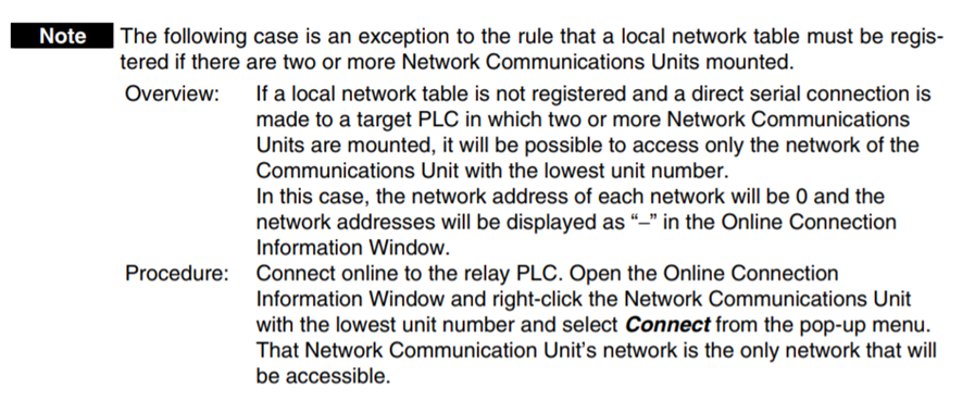
NB: A built-in Ethernet port on a PLC is classified as one communication unit!
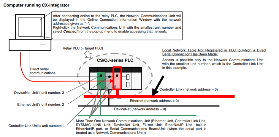
To use CX-Integrator, the computer must first connect online to a PLC connected through a direct serial/network connection or another PLC in the network (known as the relay PLC). Once the online connection is established with the relay PLC, another PLC can be specified as the target PLC and accessed through the relay PLC. Normally, the same PLC is both the relay PLC and the target PLC.
In this case the relay PLC is the target PLC, where our equipment has a NJ301 (built-in Ethernet - first communication unit) and a CJ1W-DRM21 (DeviceNet - second communication unit).
Procedure
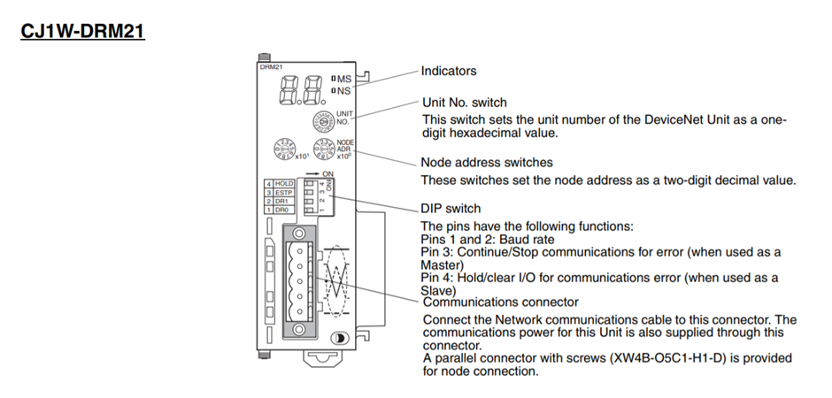
Step 1 - Setup DRM21 Rotary Dials
The default unit no of CJ1W-DRM21 is 0 and node address is default of 63. These defaults will be used for the purpose of this application note.
NB: The node address needs to be set to a value higher than 0 as this is a FINS network requirement for routing.
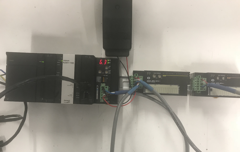
Step 2 - Connect Hardware and Power ON CPU Rack
Connect hardware together along with DeviceNet slaves and power up and connect NJ Ethernet port to PC.
Step 3 - Configure PLC IO Table
- Open a project and go online to PLC.
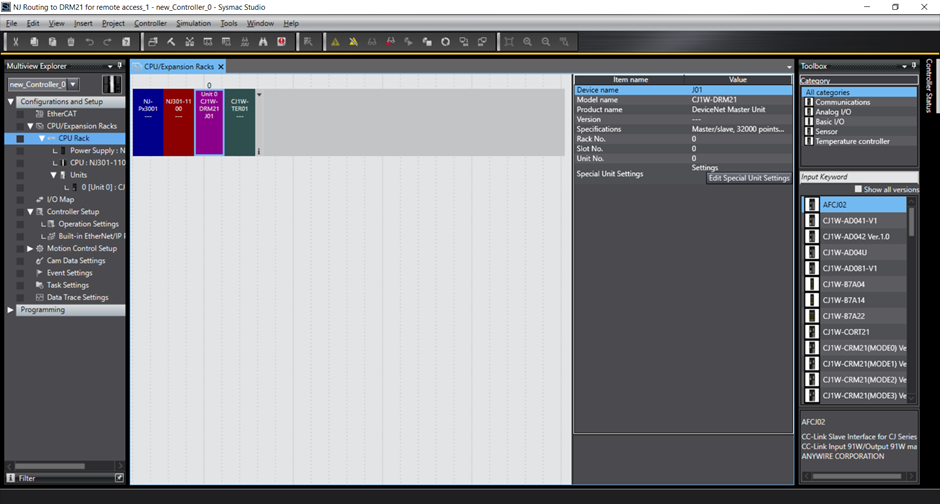
- Go to Configurations and Setup tab in Multiview explorer.
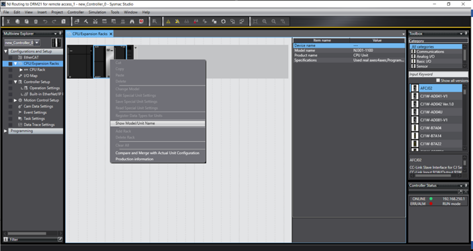
- Double click CPU/Expansion Racks and right click on CPU graphic to the right hand side.
- Select ‘Show Model/Unit Name’. (This is more for aesthetics)
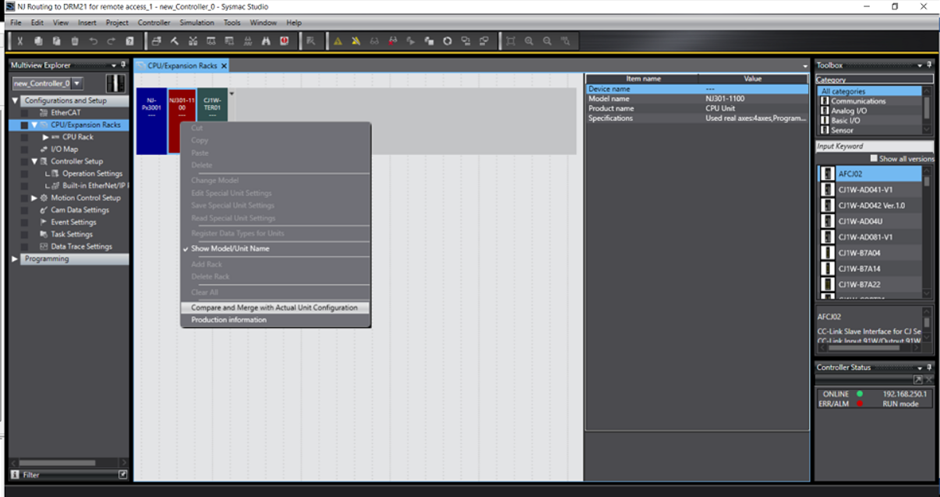
- Select ‘Compare and Merge with Actual Unit Configuration’.
- This view will show what is connected to the PLC and what is shown in the project. Select ‘Apply Actual Unit Configuration’ which will apply the connected CJ1W-DRM21 to the project IO table.
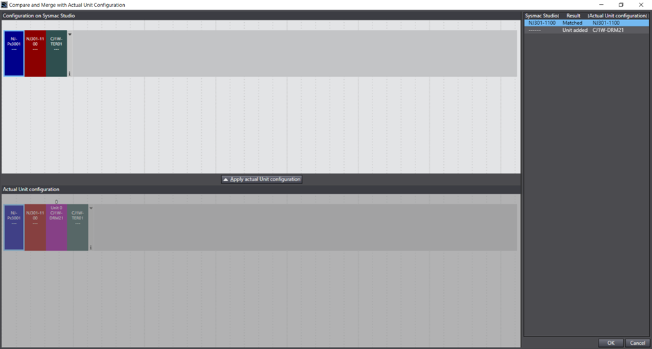
NB: Note the unit number (0) above CJ1W-DRM21 graphic - Once complete click ‘OK’
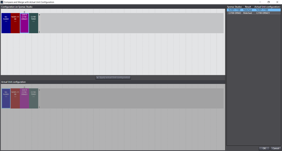
- The CJ1W-DRM21 is now added to the PLC racks IO Table within the project.
Go offline for the next step.
Step 4 - Configure Routing table for PLC Ethernet and DeviceNet networks
- Under the Multiview Explorer -> ‘Configuration and Setup Tab’ -> ‘Controller Setup’ -> Double Click ‘Operation Settings’.
- In the new window select the second vertical box -> ‘FINS Settings’. This is where the routing table needs to be entered.
- In this article we have chosen to set the PLC Ethernet port as network 1 and the CJ1W-DRM21 as network 3. (Any network number can be assigned here as long as it is unique and NOT 0!)
In this instance add as below screenshot where:
Built-in Ethernet Port (NJ301 Ethernet Port):
Unit number = Automatically assigned
Network = 1
CJ1W-DRM21 (aka CPU Bus Unit):
Unit No 0 (position of the card on the rack)
Network = 3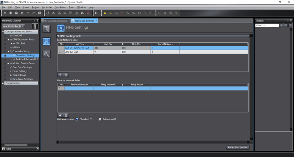
- Go Online and Transfer the Program
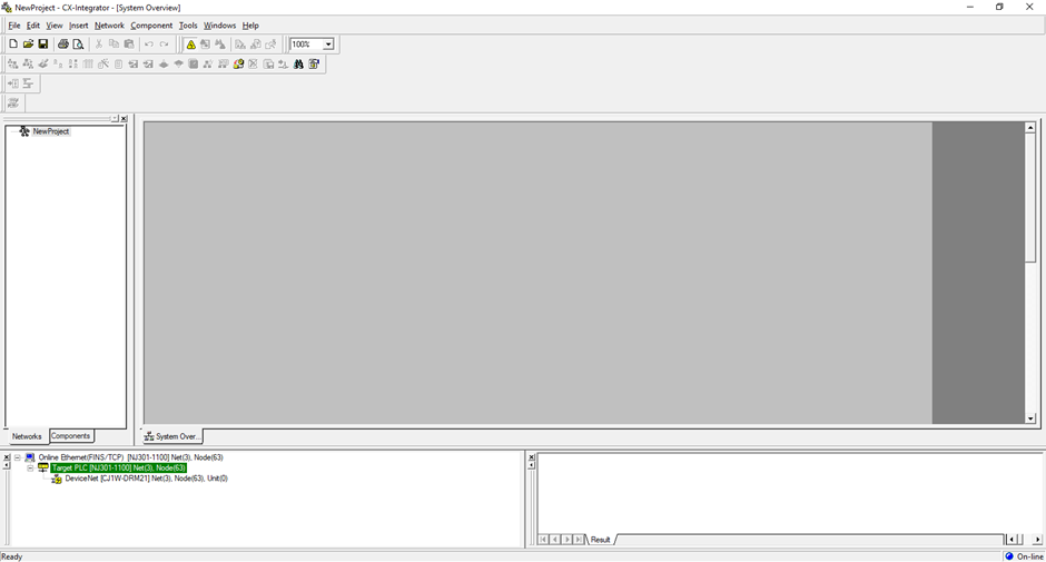
Step 5 - Open CX-Integrator and Connect to Devicenet Network
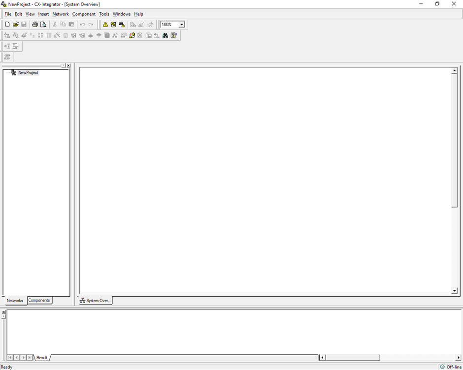
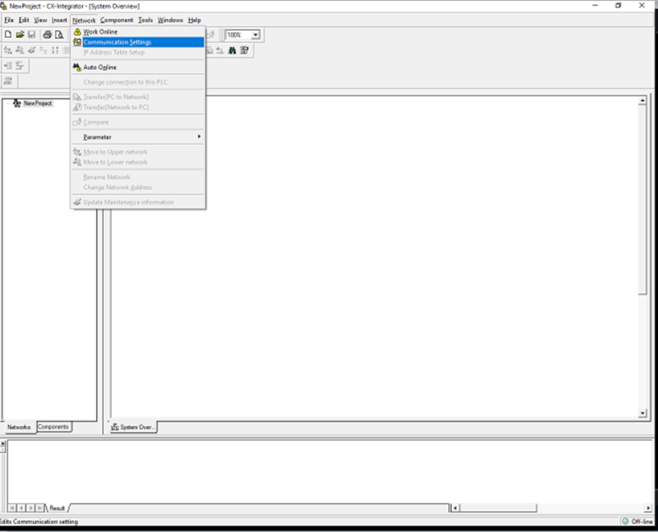
- Open CX-Integrator
- Select 'Network' -> 'Communication Settings'
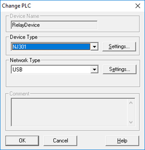
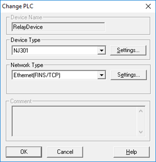
- Select NJ301 in ‘Device Type’ then select ‘Settings’ directly to right hand side:
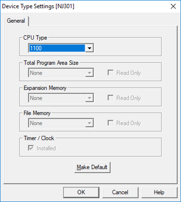
- Select ‘CPU Type’ as 1100 (NJ301-1100) then press OK:
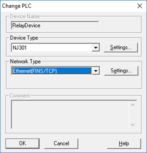
- Select ‘Network Type’ as ‘Ethernet (FINS/TCP)’ then select ‘Settings’ directly to right hand side:
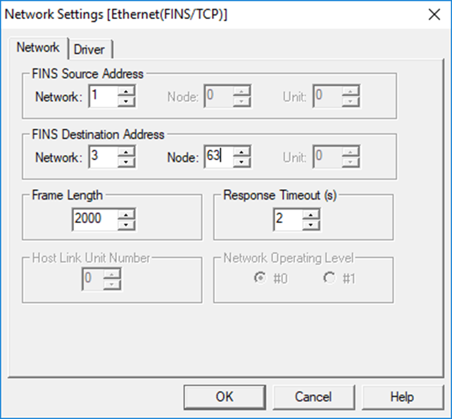
- Here you need to add:
FINS Source Network Address = 1 (Set the network address of the Ethernet network connected to the computer. In this case the NJ301 built-in Ethernet/IP Network Address as specified in NJ routing table. Use the default setting of 0 if there is only one Ethernet Unit in the PLC and only one network is being used.)
FINS Destination Network Address = 3 (Set the network address of the network connected to the PLC to which the connected communications unit is mounted. In this case the DRM21 Network Address as specified in NJ routing table. Use the default setting of 0 if there is only one Ethernet Unit in the PLC and only one network is being used.)
FINS Destination Node Address = 63 (Set the node address of the connected communications Unit. Set the node address set on the rotary switches on the communications Unit. In this case the DRM21 node address. This should be set between: 1-254)
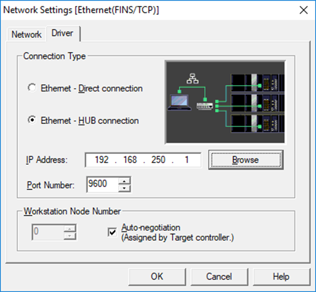
Select Driver tab and specify NJ IP address. Select OK:
Select 'OK':
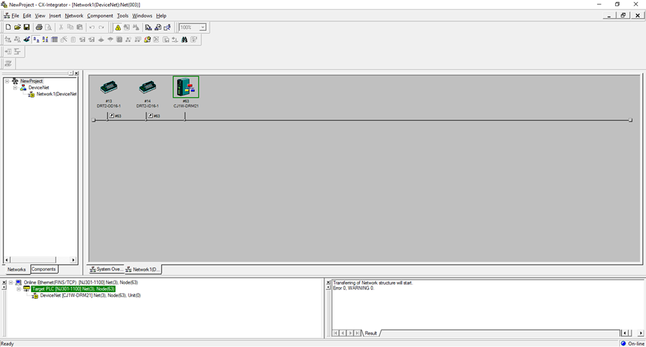
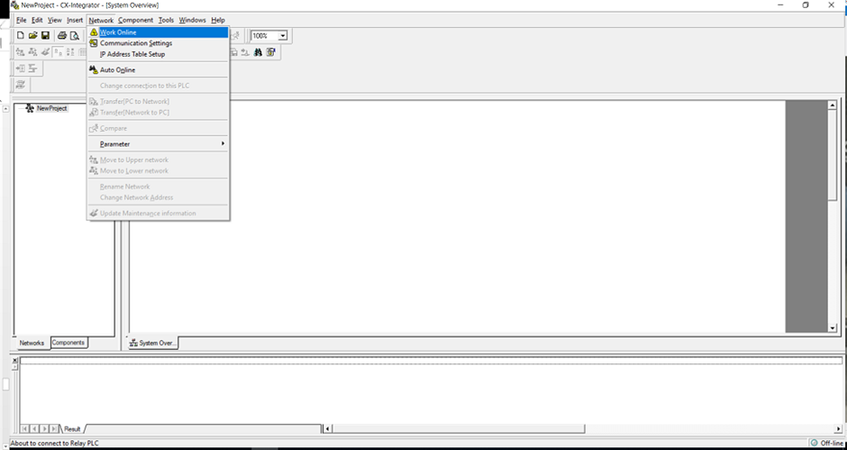
Select 'Network' -> 'Work Online' to connect to PLC network:
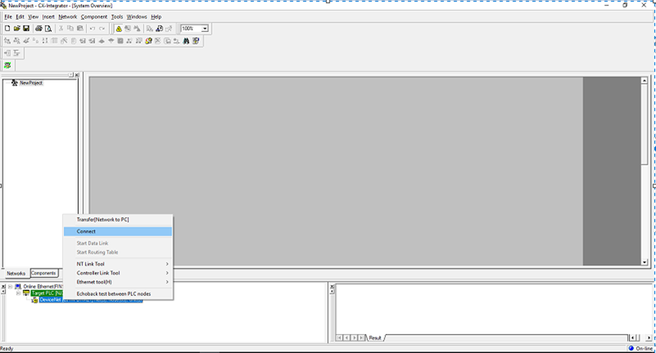
Right click on Devicenet network and select ‘Connect’:
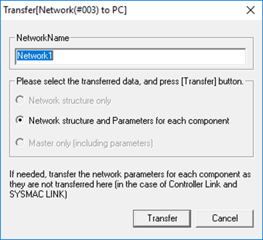
Once connected upload the network:
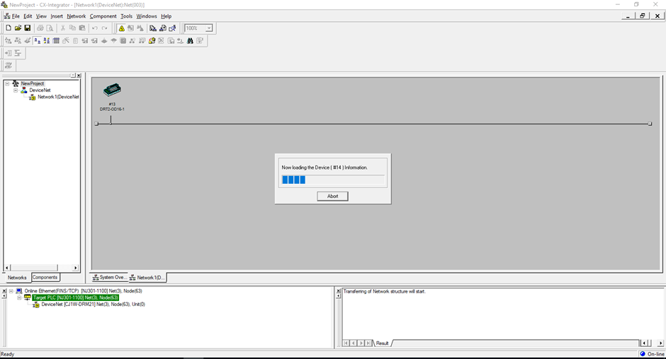
After upload you will have successfully connected to the CJ1W-DRM21 through the NJ’s built-in Ethernet/IP port with the use of a routing table.